UHF Arithmetic Unit
Zurich Instruments offers a unit for arithmetic operations on the results of lock-in amplifier and boxcar measurements. The UHF Arithmetic Unit (AU) is included with every UHF instrument; additional upgrades such as the UHF-BOX and UHF-PID options extend the instrument's functionalities even further.
The 4 arithmetic units enable real-time operations on the measurement results of demodulators, boxcar units, and auxiliary input connectors as input parameters. On the UHFLI, for example, 2 signal inputs and 8 dual-phase demodulators make it possible to combine more than 50 different input parameters. Supported operations include addition, subtraction, multiplication, division, scaling, as well as absolute-value and phase-angle calculation of complex numbers in the form X1 + i*Y2.
- 4 arithmetic units
- More than 50 input parameters
- Add, subtract, multiply, and divide demodulator samples (X, Y, R, Θ)
- Add, subtract, multiply, and divide boxcar output samples (requires UHF-BOX option)
- Conversion to polar coordinates of arbitrary Cartesian demodulator outputs
- Fixed coefficients and auxiliary inputs as scaling factors
- Results available on auxiliary output connectors and as PID inputs (requires UHF-PID option)
- Fast streaming to host computer
LabOne Integration
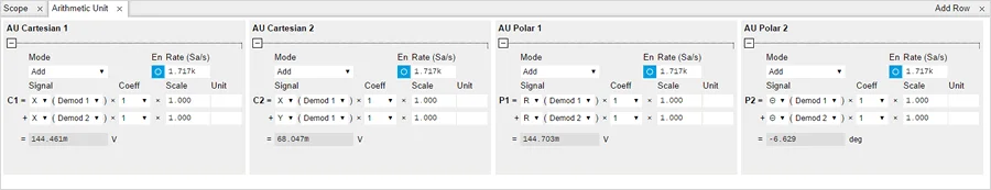
A dedicated tab in LabOne accommodates the 4 AU units. Thanks to this integration, users can monitor the results in real time and stream them to the host computer at a configurable rate for further analysis with one of the time- and frequency-domain tools of LabOne.
The use of the AU is particularly attractive for applications where the result of the arithmetic operation provides direct feedback to an experimental setup. The results can be used as an input for PID controllers (when the UHF-PID option is installed) and are available on any of the auxiliary outputs; the latter possibility means that they can be selected as demodulator inputs, enabling a second lock-in step such as tandem demodulation.
Examples of Applications
Balanced detection: noise suppression by differential measurement
\(c_0\cdot\{R_2,X_2,Y_2,\Theta_2\} - c_1\cdot\{R_1,X_1,Y_1,\Theta_1\}\)
Differential signal measurement is a powerful method for cancelling out certain noise components in order to improve the signal-to-noise ratio (SNR). This approach is powerful and can be adopted in many scenarios – for instance, in the optical domain where laser spectroscopy and imaging setups are limited by laser amplitude noise. To overcome such limitations, one can split the laser beam into a probe beam that passes through the setup and a reference beam that does not not interact with the setup; the two beams are detected by separate photodiodes (PDs). Subtracting the electrical PD signals cancels out the noise components common to both beams and, for measurements of periodic signals (pulsed lasers, etc.), removes undesired DC components and thus facilitates further signal analysis downstream. When it is not possible to place the two PDs close enough to subtract their photocurrents directly, one option is to connect them to the two inputs of the lock-in amplifier where they can be measured with two demodulators referenced to the same oscillator and with the same filter settings. Subtracting the demodulator outputs reduces the coherent noise from the signal of interest and increases the SNR.
One limitation of the scheme discussed above is that the intensity of the two light beams must be carefully matched (assuming a symmetric detection setup) to maximize noise suppression. This process of intensity matching can be tedious, and for setups where the transmission of the probe beam displays significant changes it may be useful to adopt an auto-balancing approach to maintain noise suppression over the course of a measurement. This can be realised by introducing a slowly varying scaling parameter g with a bandwidth lower than that of the actual signal (low-pass-filtered, LP): g = LP(Rsig) / LP(Rref). The resulting signal is then derived as c0 * Rsig - g * Rref, where c0 is an adjustable scaling factor maximizing performance.
Normalization and relative measurement
\(\frac{R_1}{R_2}\)
For measurements where small differences between two samples need to be detected while the signals themselves can change over many orders of magnitude – a rather common scenario for impedance and optical transmission measurements – a relative measurement that divides the two signals can help to keep track of the relevant measurement quantity. This also means that the signal can be boosted by numerical scaling independent from the actual signal levels, which is valuable when the signal is further processed with a PID controller to provide feedback to an experimental setup. In such situations, the controller parameters do not have to be readjusted every time the signal levels change. This can be used, for instance, in a spectroscopy setup where the frequency of a laser is adjusted to obtain the optical transmission of a gas cell.
Modulation parameter output for AM and FM signals
\(R_m=\frac{\sqrt{(X_2+X_3)^2+(Y_2+Y_3)^2}}{R_1}\) (AM modulation with normalization)
\(R_m=\frac{\sqrt{(X_2-X_3)^2+(Y_2-Y_3)^2}}{R_1}\) (FM modulation with normalization)
\(h_{AM}=\frac{X_1}{X_2}\) (AM modulation index)
The analysis of signals with multiple frequencies such as amplitude-, frequency-, or phase-modulated signals can be conveniently achieved with direct sideband extraction. The UHF-MOD option provides the demodulated outputs X, Y for the carrier (demodulator 1) and the sidebands independently (demodulator 2 and 3). Whenever an experiment requires the entire signal contained in the two first sidebands, this is then easily determined (even normalized to the carrier). The sum (for AM) or difference (for FM) of the sidebands improves the SNR by a factor of √2 compared to the measurement of one sideband only.
Dual frequency resonance tracking (DFRT)
\(R_1-R_2 \)
Reliable resonance frequency tracking often relies on phase-locked loops that exploit phase information to provide fast feedback. However, the SNR ratio of the phase signal may be insufficient for feedback or may be ambiguous due to specific physical properties (as seen in near-field scanning of polar materials, where the phase flips by 180 degrees at the domain boundaries).
Instead of relying on the phase signal, it is possible to probe the resonance with two frequencies detuned so as to hit the steepest slopes right and left of the resonance center frequency. The difference of the two amplitude signals then provides an error signal to a PID controller (when the UHF-PID option is installed). This blog post on the DFRT method provides more details about the practical implementation of this technique.