Bell-State Stabilization of Superconducting Qubits with Real-Time Feedback
Bell-state stabilization with real-time feedback is a key milestone for the implementation of surface code [1], which is one of the most promising quantum error correction codes for building large-scale quantum computers [2]. Fundamental requirements for realizing this code are high fidelity and rapid readout of qubits, high fidelity gate operations, and performing conditional feedback with latency times much shorter than the qubit coherence times. Thanks to its three products UHFQA, HDAWG and PQSC, Zurich Instruments fulfills all of these requirements.
As a practical application of low latency real-time quantum feedback, we have shown in a previous blog post how rapid qubit initialization can be easily achieved using the Register Forwarding feature of the PQSC. In this blog post, we demonstrate how to realize Bell-state stabilization using the Lookup Table Decoder of the PQSC. For this purpose, we detect arbitrary errors on a pair of entangled data qubits in a Bell state by reading out another pair of ancilla qubits using a UHFQA. The readout results are forwarded to the PQSC for further processing and generation of feedback decision. The decision is then communicated to the HDAWGs and used for waveform selection to send out the necessary control signals to restore both the data qubits and ancilla qubits back to their original states.
Introduction
Quantum computing is expected to be a game-changing technology that will unlock solutions to problems that are practically impossible to solve with classical computers. However, bringing this technology into reality is not without challenge. The qubits that make up a quantum computer are well known to be unstable due to interactions with the environment and prone to errors caused by imperfect quantum gates. To implement a useful and viable quantum computer, it is essential to find ways to deal with these errors.
To achieve sufficiency low error rates that a practical quantum computer requires, researchers keep improving the quality of qubits to make them more stable and less susceptible to errors. However, even the best qubits today are not good enough to be directly used in quantum algorithms. One way to compensate for high error rates of qubits is to add redundancy and encode one logical qubit within several physical qubits. In other words, a set of unreliable physical qubits works collectively as one reliable logical qubit. This way, errors can be detected and fixed as they pop up in individual physical qubits without affecting the state of the logical qubit.
Known as quantum error correction code, this method basically creates quantum links between two types of physical qubits, namely the data qubits, which encode the logical qubit and store its state, and the so-called ancilla qubits, which are used to detect errors on the data qubits. Each ancilla qubit is entangled to its neighboring data qubits, which maps the parity of these data qubits on to that ancilla qubit. By using repetitive measurements on an ancilla qubit, which is the quantum equivalent of parity checks, it is possible to find out whether the neighboring data qubits have undergone bit-flips or/and phase-flips relative to each other. Since the data qubits are not measured directly, their states are preserved during the parity measurements, assuming no errors have occurred. If an error is detected on a data qubit, it should be flipped back to its original state.
A complete quantum error-correcting code must be able to tackle both types of errors that can affect qubits: bit-flips and phase-flips. Detecting either only bit-flip or phase-flip errors can be realized with a simple error correction code, called repetition code, consisting of qubits arranged in a linear array, as shown in Figure 1.

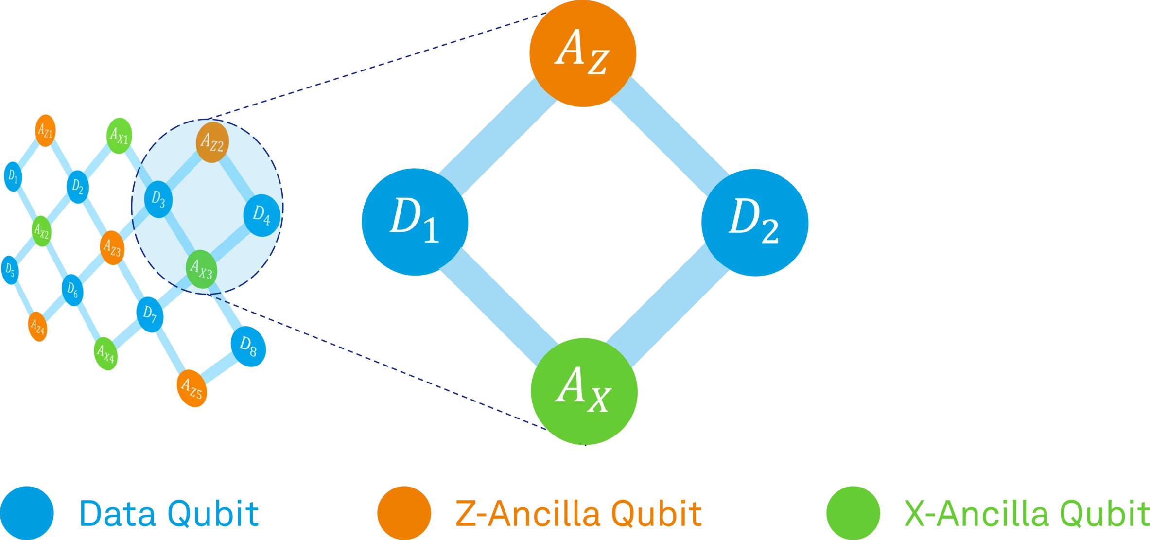
Accounting for both error types simultaneously requires, however, extending the code to higher dimensions. The surface code (SC), which is a two-dimensional array of data and ancilla qubits, is the most prominent candidate so far to achieve this. Figure 2 shows a basic layout of surface code.

The simplest system having the basic properties of a two-dimensional array is a two-by-two planar lattice of four qubits, as can be seen in Figure 3. It can perform the so-called Bell-state stabilization, which detects and corrects both bit-flip and phase-flip errors concurrently on two data qubits prepared in a Bell state. Bell-state stabilization can be seen as a primitive tile of the surface code as it represents a building block towards larger lattices of surface code.
Concept
Before we go into the details of the actual experiment, let's cover a few important concepts.
Entangling two qubits in a Bell state
The Bell states are the simplest example for entanglement of two qubits. They are also referred to as maximally entangled states, which means that the two qubits in a Bell state exhibit perfect correlation. There are actually four different Bell states, but each of them works similarly. For simplicity, we will focus only on one of them: the in-phase combination of |00⟩ and |11⟩. Figure 4 shows how two qubits can be prepared in a Bell state.
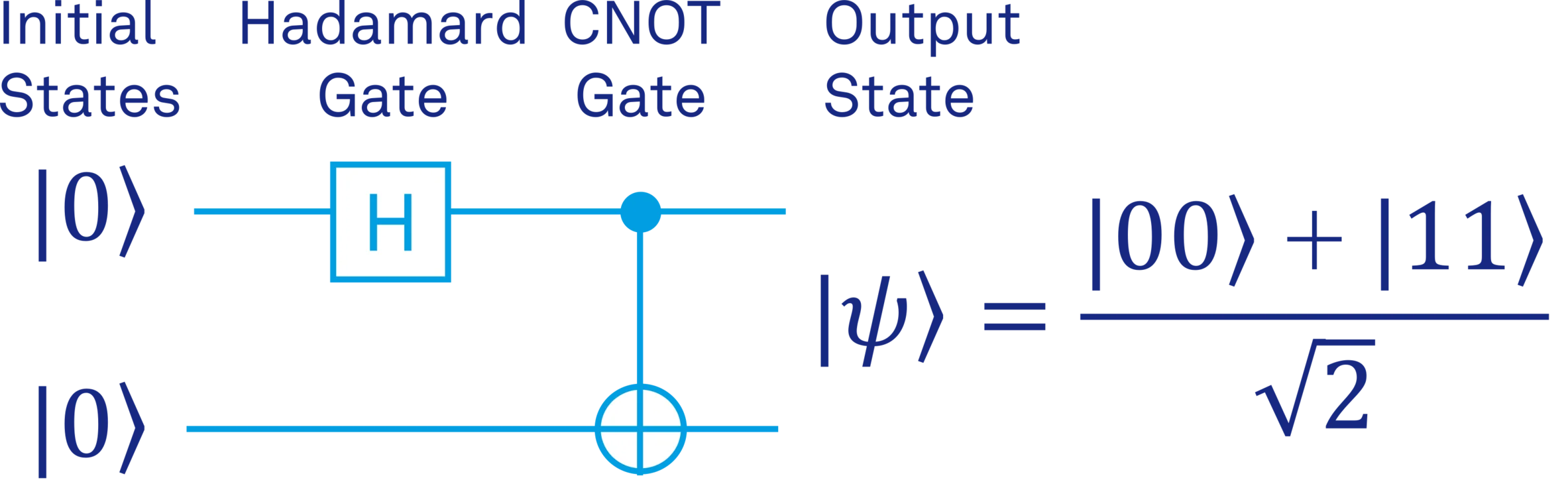
The two qubits are initialized in the state |00⟩. A Hadamard gate acts on the first qubit and brings it into a superposition of the states |0⟩ and |1⟩. The two-qubit CNOT gate inverts the target qubit (⊕) from ∣0⟩ to ∣1〉 only if the control qubit (•) is in the state ∣1〉. Hence, the desired entangled state is obtained as shown at the output.
Stabilizing a Bell state
In addition to being a significant step towards the surface code implementation, the Bell state stabilization is also essential for many other applications of quantum information. Two qubits in a Bell state show very strong correlations that cannot be explained with classical physics. This characteristic is often exploited to enable tasks such as super-dense coding, quantum teleportation and quantum cryptography. Despite being very useful, the Bell states are usually difficult to prepare and sustain in real life, since the environment-induced decoherence causes the qubits to lose their entangled state. Therefore, it is very important to protect the Bell state against errors.
Real-time stabilization of a Bell state can be achieved by using an active feedback loop, which can be summarized in three steps:
- Performing repeated bit and phase parity measurements using the ancilla qubits to detect errors.
- Applying feedback operations conditioned on the outcome of the parity measurements to correct the errors.
- Resetting the ancilla qubits and preparing for the next round.
Let's investigate these steps in a bit more detail to better understand how it works.
Detecting the error
The ancilla qubits can be divided into two types: bit-flip ancilla (or Z-ancilla) and phase-flip ancilla (or X-ancilla). Each type of ancilla qubit is coupled to the two data qubits with CNOT gates. Figure 5 shows how the bit (ZZ) parity of the two data qubits can be encoded on the Z-ancilla qubit.

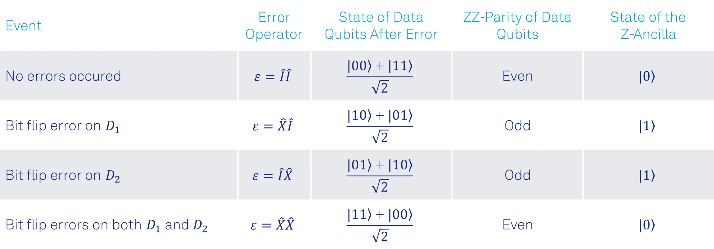
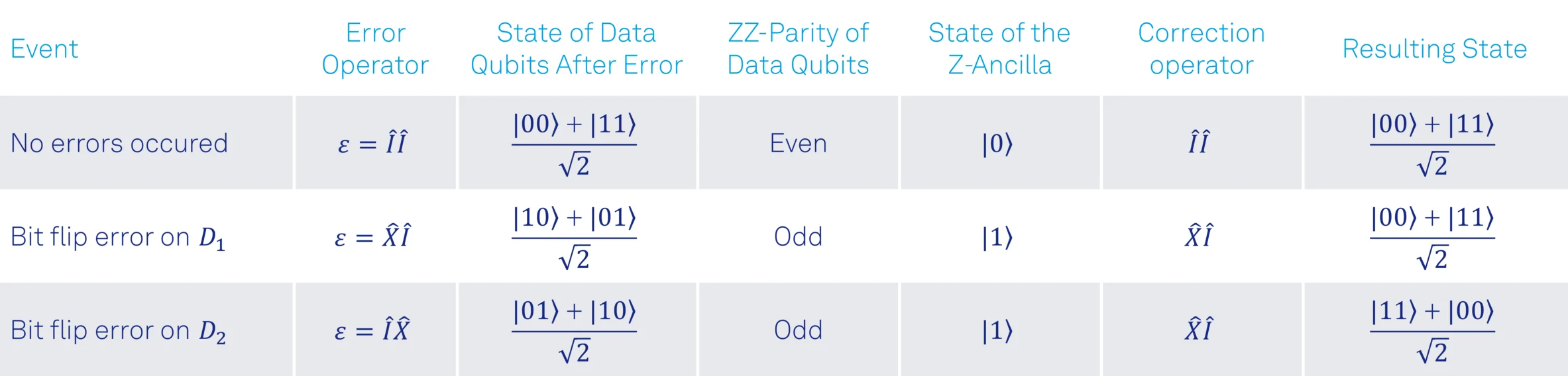
First, the data qubits are initialized in the two-qubit entangled state. To represent the effects of imperfect physical qubits, an arbitrary error ϵ is shown to act on the data qubits after the state preparation. The ancilla qubit is initialized in the state |0⟩ and two CNOT gates are used to encode the bit (ZZ) parity of the data qubits on it. If the parity of the two data qubits is even, which is the case if no bit-flip errors have happened, the ancilla qubit will remain in the state |0⟩. However, if a single bit flip error occurred on either of the data qubits, the ancilla qubit will be flipped to the state |1⟩. Finally, the measurement of the ancilla qubit will tell if the two data qubits are in the even or odd parity state, from which we can find out if an error has occurred or not.
Table 1 provides examples for single bit-flip errors occurring on different data qubits and the measurement result of the ancilla qubit as a result of the occurred error.
Remarks:
- If bit-flip errors occur on both data qubits simultaneously, the parity measurement will indicate that we are in an even parity state, and we will not be able to detect any errors. Nevertheless, simultaneous bit-flip errors on both qubits keep them in the Bell state, as can be seen in Table 1. Even if this was not the case, we could assume here that simultaneous errors on both data qubits are relatively rare, provided that the probability of a bit-flip error on each of the data qubits is small enough [a].
- Detecting an odd parity reveals that a bit-flip error has occurred, but we don't know on which data qubit the error has occurred. However, we will see that this information is not necessary to restore the data qubits back to the original Bell state.
We can extend the circuit in Figure 5 to add the phase (XX) parity encoding of the two data qubits on the X-ancilla qubit, as shown in Figure 6.
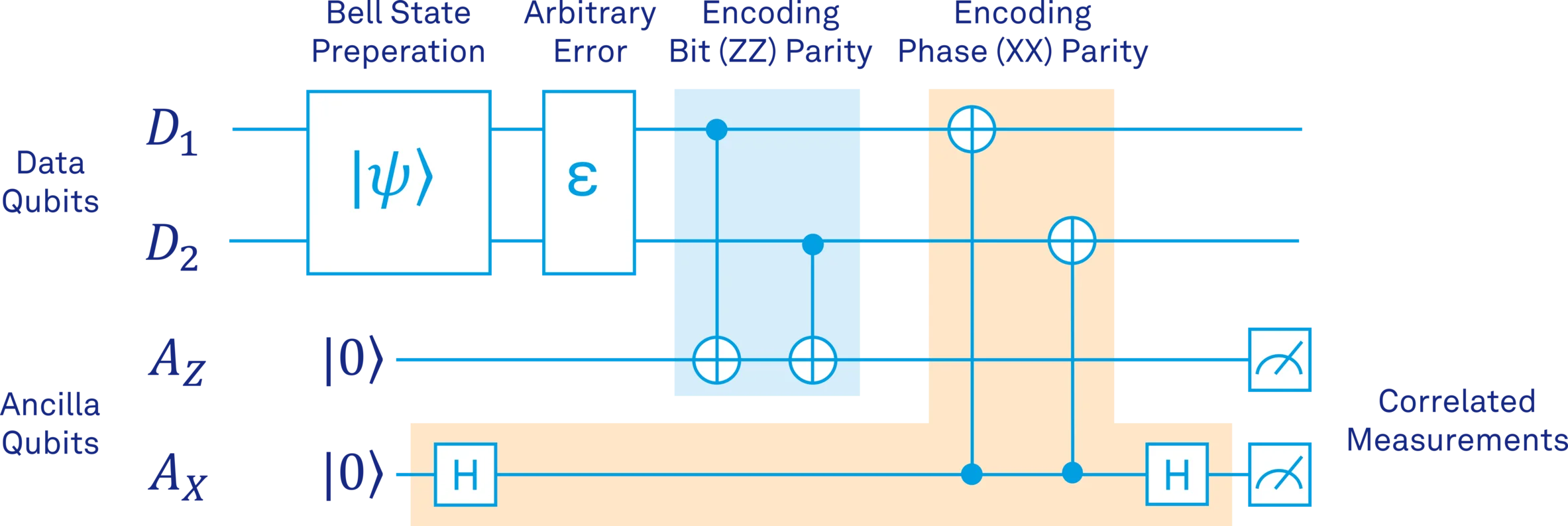
As shown in Figure 6, the bit parity encoding can easily be changed to phase parity encoding by adding two Hadamard gates (before and after the CNOTs) and inverting the direction of the CNOT gates. Analysis of the measurement result of X-ancilla is essentially the same as Z-ancilla, except that measuring the X-ancilla in the state |1⟩ will indicate that a phase-flip error has occurred on one of the data qubits.
Correcting the error
The detection step tells us whether a bit-flip or phase-flip error has occurred on the data qubits. However, it does not reveal on which qubit the error has occurred. How can we then reverse the error and recover the original Bell state? It turns out that the correction operation to restore the Bell state does not depend on where the error has happened. Let's extend the examples in Table 1 to demonstrate how to correct the single bit-flip errors occurring on different data qubits.
As can be seen from Table 2, applying the correction operator always on data qubit D1 restores the data qubits back to the original Bell state regardless of where the bit-flip error has initially occurred. This is valid for single phase-flip errors occurring on different data qubits, as well. Table 3 provides examples for single phase-flip errors occurring on different data qubits and the necessary correcting operator to restore the original Bell state.
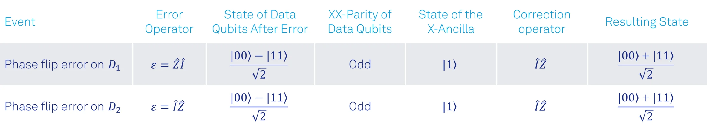
Similar to bit-flip errors, applying the correction operator always on data qubit D2 restores the data qubits back to the original Bell state regardless of which qubit has undergone the phase-flip error.
Preparing for the next round
After applying the correction operators, the qubits must be prepared for the next feedback round. First, if an ancilla qubit is measured in the state |1⟩, it must be restored to the state |0⟩. And finally, the encoding procedure has to be repeated to encode the bit and phase parities of the data qubits on the ancilla qubits again.
Tabletop Demonstration
To give an overview of the feedback data processing functionalities of the PQSC and test our Bell-state stabilization protocol before starting with real laboratory experiments, we use the setup shown in Figure 7 to perform a tabletop demonstration. This setup consists of a PQSC for the feedback data processing, a UHFQA for qubit readout and two HDAWGs for sending out control signals. To verify the results, we use an oscilloscope to view the readout pulses and the control signals sent out from the HDAWGs. For simplicity, the up- and down-conversion of the readout and control signals is omitted here.

For the readout of the ancilla qubits, we use the UHFQA Quantum Analyzer. This instrument is designed for parallel readout of up to ten superconducting qubits on a single microwave line, with high speed and fidelity, as required for quantum error correction experiments. Since we have only two ancilla qubits to read out, we will use just two of the ten readout channels on the UHFQA. Alternatively, the Zurich Instruments SHFQA can also be used for the readout of ancilla qubits. Its main advantages over the UHFQA are the larger number of qubits (up to 64 qubits) that it can readout and the integrated up- and down conversion to generate the high frequency signals required for the typical readout resonators of superconductive qubits without the need for mixer calibration.
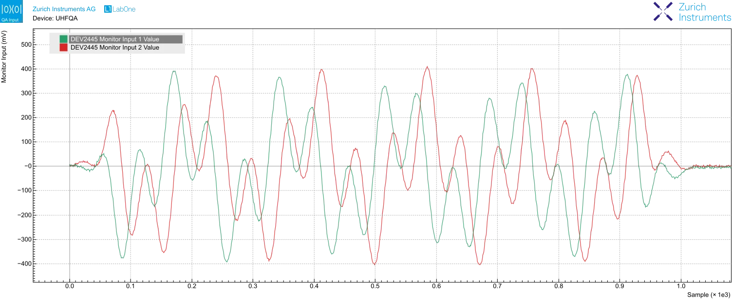
As can be seen in Figure 7, we connect the two signal outputs of the UHFQA to the two inputs in a closed loop to perform a simulated qubit readout. We simply mimic the qubit-state dependent resonator response by adding a phase offset of 180° to the I and Q quadratures of the measurement tone corresponding to a qubit to simulate it as in the state |1⟩. If no phase offset is added, the qubit is simulated as in the state |0⟩. For more detailed information on simulated qubit readout, please refer to this blog post.
Figure 8 shows the I and Q signals of a readout pulse composed of two frequencies of respectively 10 and 31.5 MHz, with 0° phase offset to simulate both qubits in the state |0⟩.
The UHFQA sends the readout results to the PQSC. They are first sent to HDAWG 1 via a fast digital interface called DIO. Then, HDAWG 1 automatically forwards them to the PQSC with its ZSync connection, as shown in Figure 7.
In an experiment, the PQSC connects with all the HDAWGs (or SHFSGs) used for the qubit control and with all the UHFQAs (or SHFQAs) used for qubit readout. All the communications are done over ZSync links, which have four roles:
- Provide a common reference clock for all instruments.
- Send out trigger signals to the qubit control and readout instruments to synchronize them to sub-nanosecond levels.
- Provide a data interface to send qubit readout results from the UHFQAs (or SHFQAs) to the PQSC for processing.
- Provide a data interface to send the processed feedback data from the PQSC to HDAWGs (or SHFSGs).
The PQSC feedback architecture, shown in Figure 9, processes the incoming data in several stages:
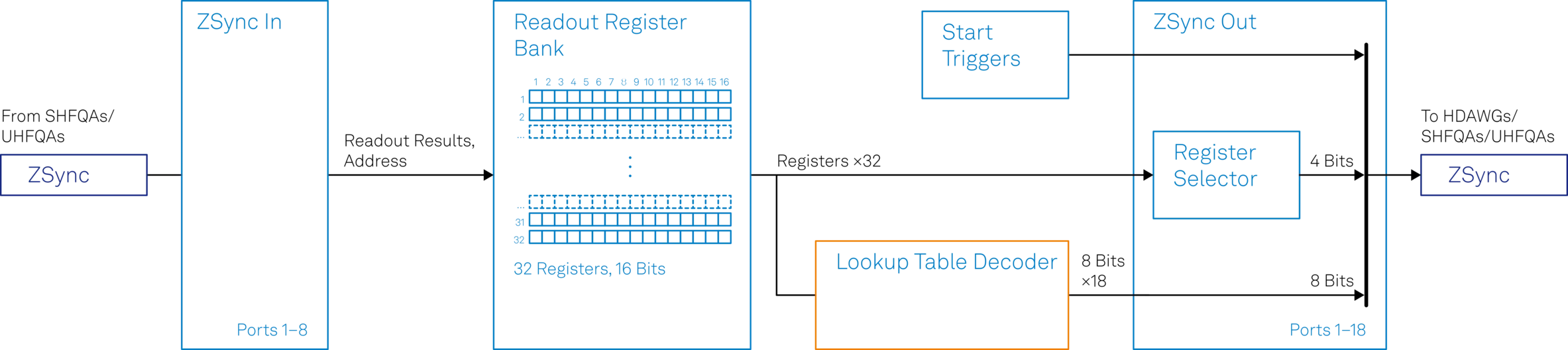
- When the UHFQA (or SHFQA) performs a readout and sends the results to the PQSC, these results are written into the Readout Register Bank.
- The whole Readout Register Bank content is forwarded to the Lookup Table (LUT) Decoder unit for further processing.
Inside the LUT Decoder, shown in Figure 10, the Readout Register Bank content is processed as follows:

- The Source Register Selector selects 16 readout results from the content of the Readout Register Bank.
- The selected results are used to create an address word of 16 bits.
- The address word is used to access the entries of the look-up table.
As we discussed in a previous section, quantum error correction requires parity measurements performed on the ancilla qubits. The results of the parity measurements are then used to evaluate the error decoding function to deduce which errors have occurred and the necessary feedback action to correct them. Here, this evaluation is performed by the LUT Decoder unit of the PQSC using two readout results selected by the Source Register Selector and the look-up table programmed by the user.
Remark:
- For very low-latency real-time quantum feedback experiments the feedback action based on readout results must be calculated very fast. The fastest way to calculate the feedback action is actually not to calculate it at all – but to simply “look it up” from a look-up table, hence the name. A look-up table is a basic memory block that stores precalculated values. Each stored value can easily be retrieved by specifying its address. As already implied above, the biggest advantage of a look-up table is that it works very fast since the time required to retrieve a stored value is much shorter than calculating it in real-time.
Let’s use an example to see how the register selection and accessing the look-up table exactly works.

Figure 11 shows a Readout Register Bank filled with results sent from the UHFQA, such that:
- Readout result of Z-ancilla qubit → Register 2, Bit 1 of Readout Register Bank
- Readout result of X-ancilla qubit → Register 2, Bit 2 of Readout Register Bank
- 0 → All other bits of Readout Register Bank (by default after reset)
The Source Register Selector is configured such that:
- Register 2, Bit 1 of Readout Register Bank → Bit 0 of Address Word
- Register 2, Bit 2 of Readout Register Bank → Bit 1 of Address Word
- Register 1, Bit 1 of Readout Register Bank → All other bits of Address Word (by default)
The entries of the look up table correspond to the feedback actions conditioned on the readout results. Therefore, while programming the look-up table, we need to account for every possible combination of readout results of the ancilla qubits. Since we have two ancilla qubits, there are a total of 2^2 = 4 possible combinations of the readout results. Hence, the look-up table has 4 entries. Table 4 shows which entries of the look-up table will be accessed depending on the readout results of the ancilla qubits.
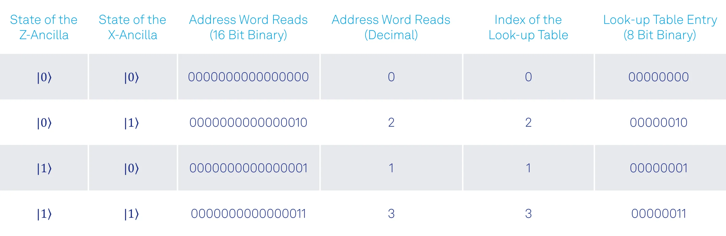
The output of the feedback data processing is one of the entries of the look-up table. It is an 8-bit binary number, which is forwarded to the selected HDAWGs (or SHFSGs). Whenever a new readout result is available from the UHFQA, the LUT Decoder processes them in a short and constant time and forwards the new output to the HDAWGs together with a trigger signal.
The HDAWG comes with either four or two AWG cores. Each AWG core can be used to send microwave pulses to the charge control line of a single qubit to perform single qubit rotations. We assign these cores as follows:
- HDAWG 1, AWG Core 0 → Data Qubit D1
- HDAWG 1, AWG Core 1 → Z-Ancilla Qubit
- HDAWG 2, AWG Core 0 → Data Qubit D2
- HDAWG 2, AWG Core 1 → X-Ancilla Qubit
The unassigned AWG cores can be used to generate flux pulses for tuning the qubit frequencies to implement two-qubit gates, for instance, the CNOT gates required for Bell state preparation and parity mapping.
The 8-bit feedback data obtained from the PQSC will pass through a configurable demultiplexer inside the AWG core to select the portion of interest. Please refer to the PQSC User Manual and the attached Python script for detailed information related to the configuration of the demultiplexer.
After the portion of interest in feedback data is selected, it will be used to address the command table to play a waveform. Please refer to this blog post for detailed information related to command table entry execution based on feedback data.
Whenever there is a bit-flip error on one of the data qubits, we correct it by sending a Rxπ pulse from AWG core 0 of HDAWG 1 to data qubit D1. Phase-flip errors, on the other hand, are corrected by sending a Rzπ pulse from AWG core 0 of HDAWG 2 to data qubit D2.
Results
As an example, we demonstrate four rounds of error correction, where we cycle through all possible combinations of ancilla qubit states in the simulated readout sequence. In each round, we perform real-time feedback conditioned on the ancilla measurement results to stabilize the two data qubits in a Bell state and to actively reset the ancilla qubits back to the state |0⟩.
Remark:
- For the sake of simplicity, we omit the initial Bell state preparation and the parity mapping (for preparation of the next round) between the rounds.
Figure 12 shows the scope measurement traces of the simulated resonator responses from the UHFQA and the feedback pulses from the HDAWGs. For demonstration purposes, we represent the feedback pulses as follows:
- Rxπ → Rectangular pulse of amplitude 0.5V
- Rzπ → Rectangular pulse of amplitude -0.5V
- No feedback action (identity I) → Rectangular pulse of amplitude 0.25V
Remark:
- The control pulses shown here are only for illustration and they do not represent the real waveforms used in experiments. In particular, we are leaving out the decomposition of Rzπ gate into Rx and Ry rotations for simplicity and show the identity gate as a rectangular pulse for better visualization, although it would be a waveform of zeros in reality.
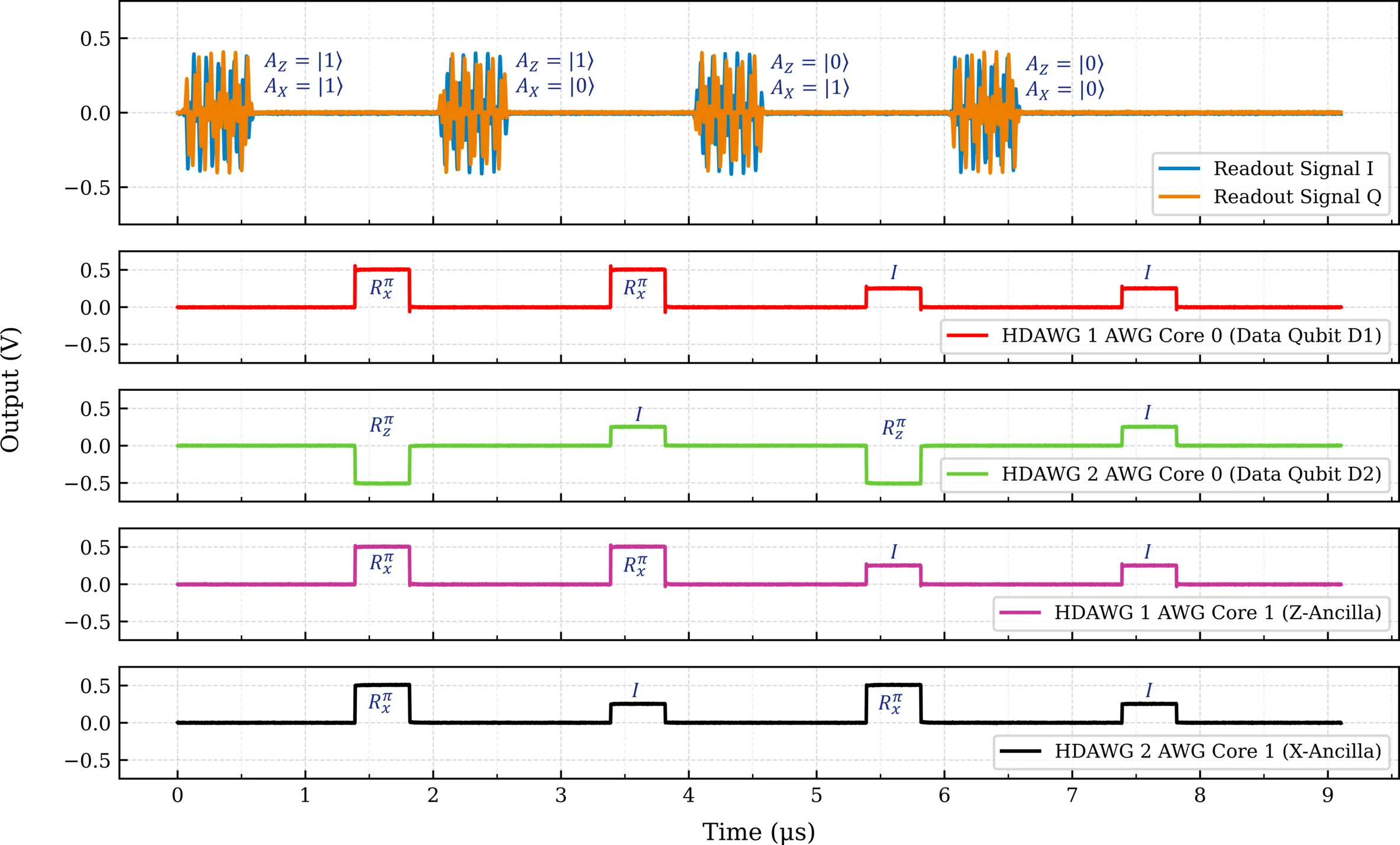
As shown in Figure 12, whenever the Z-ancilla is measured in the state |1⟩, an Rxπ pulse flips the state of D1. In this case, Z-ancilla is actively reset to the state |0⟩ to prepare for the next round. Similarly, the phase of D2 is flipped with an Rzπ pulse, whenever the X-ancilla is measured in the state |1⟩. Once again, the X-ancilla is flipped back to the state |0⟩ with an Rxπ pulse. As a result, the data qubits are restored to the initial Bell state as expected.
Conclusion
In this blog post, we demonstrated a practical application of low latency real-time quantum feedback using the Lookup Table Decoder of the PQSC. We performed simultaneous bit- and phase-parity checks by measuring two ancilla qubits and combined this with conditional real-time feedback on data qubits to stabilize a Bell state.
Even if the Bell-state stabilization is a simple algorithm with a limited number of qubits, it is an important step towards quantum error correction experiments with possible extensions to much larger surface code lattices. In fact, the PQSC is capable of scaling up to 100 qubits since it supports the synchronization of 18 HDAWGs (or SHFSGs) for qubit control and its 16-bit wide LUT Decoder can process readout results from 16 ancilla qubits simultaneously to perform more complex error syndrome decoding tasks.
Use the attached Python script now (based on zhinst-qcodes) to test our example of quantum error correction for Bell-state stabilization. And if you have any questions, don’t hesitate to get in touch with us.
References
- Córcoles, A., Magesan, E., Srinivasan, S. et al. Demonstration of a quantum error detection code using a square lattice of four superconducting qubits. Nat Commun 6, 6979 (2015). https://doi.org/10.1038/ncomms7979
- Erhard, A., Poulsen Nautrup, H., Meth, M. et al. Entangling logical qubits with lattice surgery. Nature 589, 220–224 (2021). https://doi.org/10.1038/s41586-020-03079-6
- Kelly, J., Barends, R., Fowler, A. et al. State preservation by repetitive error detection in a superconducting quantum circuit. Nature 519, 66–69 (2015). https://doi.org/10.1038/nature14270
- Andersen, C.K., Remm, A., Lazar, S. et al. Repeated quantum error detection in a surface code. Nat. Phys. 16, 875–880 (2020). https://doi.org/10.1038/s41567-020-0920-y
- Andersen, C.K., Remm, A., Lazar, S. et al. Entanglement stabilization using ancilla-based parity detection and real-time feedback in superconducting circuits. npj Quantum Inf 5, 69 (2019). https://doi.org/10.1038/s41534-019-0185-4
Footnotes
a. Let's consider an example to make it clearer. If there is a 10% chance (p=0.1) of a bit-flip error on each of the data qubits, here are the total probabilities for different cases:
- No error: (1-p)*(1-p) = 0.9*0.9 = 0.81 = 81%
- Only one error on one qubit: p*(1-p) + (1-p)*p = 0.1*0.9 + 0.9*0.1 = 0.18 = 18%
- Errors on both qubits p*p = 0.1*0.1 = 0.01 = 1%
In summary, the probability of having zero or one bit-flip error on one of the qubits is 99%. On the other hand, the probability for simultaneous bit-flip errors on both qubits is only 1%.