From First Cooldown to Two-Qubit Gates: How to Bring Up a New Novera QPU with LabOneQ’s Automation Framework
Realizing two-qubit gates on a new quantum processor, especially one with tunable qubits and tunable couplers, can be an extremely time-consuming task. You must first find all qubits, calibrate single‑qubit operations, tune the couplers, re‑calibrate the single‑qubit operations, and only then can you calibrate the two‑qubit interactions. All of this must be done prior to starting your real experiments to probe fundamental science questions or run your algorithm of interest. Automation is a key requirement to streamline this process, as Zurich Instruments has shown with our LabOne Q automation framework on a variety of qubit platforms (most recently in collaboration with Fraunhofer EMFT). This flexible framework allows each user to customize experiments, analysis, and quantum elements to fit their devices. Through the Novera QPU Partner Program, we got an early look at Rigetti’s newest nine-qubit device design and customized an automation workflow to bring up the 9-qubit device from first cooldown to realizing a two-qubit resonant Controlled-Z (CZ) gate.
In this latest design, the 9-qubit chip is optimized for CZ two-qubit gate operations, with 9 tunable transmon qubits in a 3x3 array with 3 readout lines. Each qubit is connected in a square lattice with tunable symmetric couplers. In LabOne Q, this translates to a QPU topology that contains a total of 21 custom quantum objects (9 tunable transmon objects and 12 tunable coupler objects) each with an easily customized set of parameters and operations. This platform is ideal for researchers, both brand new and experienced, looking for a flexible system to learn quantum computing fundamentals or explore new phenomena.
Isolating All 9 Qubits
Our previous blog posts have detailed many of the experiments required to tune-up single-qubit operations (from qubit and resonator spectroscopy through T1, T2-echo, and 1Q RB), all of which are included in our open-source Applications Library. These single-qubit experiments are directly translatable across different QPU designs, but they do not tell the whole story when first bringing up the Novera QPU. How this chip design differentiates from previous examples is the inclusion of symmetric couplers with the max coupling strength located at the zero-voltage coupler-flux bias, which causes the qubits to initially be in a highly interactive state when the QPU is first cooled down. Due to this initial highly interactive state, it is not possible to fully characterize individual qubits in parallel, in addition to the T2 coherences being greatly limited by the phase interactions with neighboring qubits. Before the full capabilities of the Applications Library1 can be utilized, each qubit needs to be isolated from its neighbors.
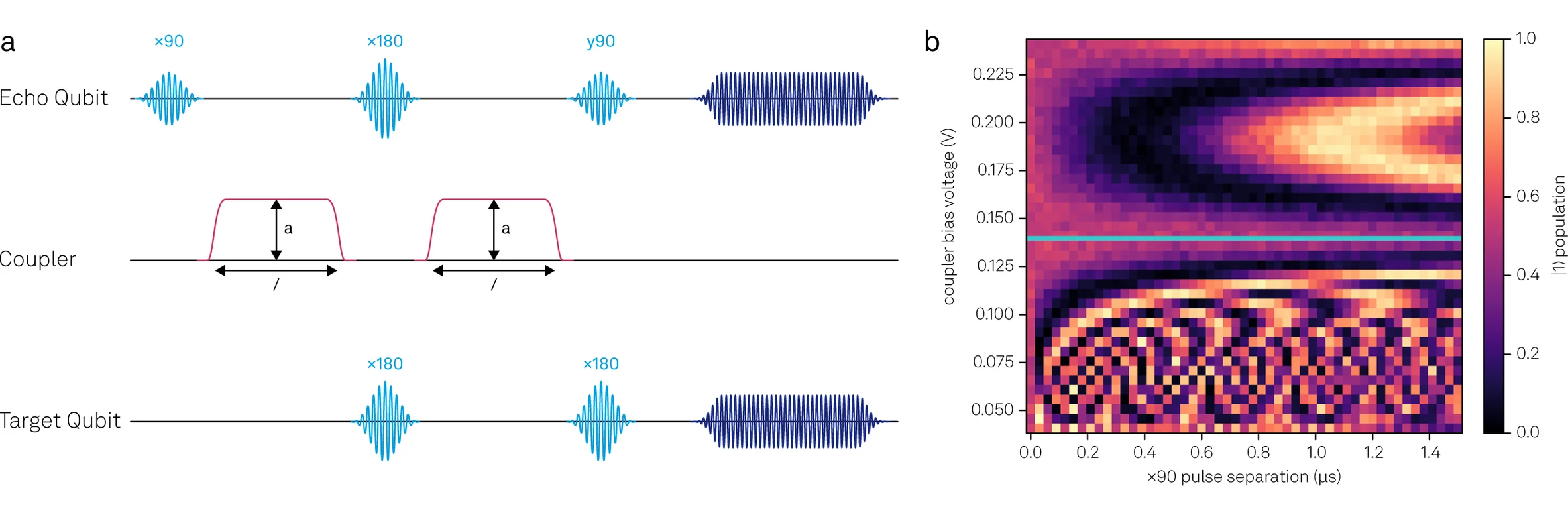
To achieve this isolation, we need to find the optimal coupler-flux bias points to minimize interactions between all qubits, allowing for us to calibrate the QPU fully in parallel and measure representative T2 coherence. The first step was to perform a full single-qubit bring-up at an intermediate coupler bias point (in this case +100 mV on all couplers). This 100 mV starting point is chosen based on the design of the couplers – in this regime the coupling is significantly reduced without extensive flux optimization. The single-qubit bring-up was fully automated using the DAG framework ran serially, using the fabrication design parameters provided by Rigetti as starting values, calibrating the drive pulses and optimizing read-out. To find the minimum-interaction point (ZZ-coupling = 0), we performed a modified ZZ-Echo experiment (Fig 2a). In this experiment, we sweep2 the flux bias and flux length applied to the coupler with the opposite qubit either in the |0⟩ or |1⟩ state. At each bias point we measure the Echo qubit to determine the phase shift when the Target qubit is in the ground and excited state. This experiment was performed on every edge to isolate each qubit from its neighbors. This isolation point can be found where there are no oscillations in the Echo qubit (located at the teal line in Fig 2b), in other words, the state of the target qubit and the coupler flux pulse do not impact the phase shift of the Echo qubit.
After minimizing coupling between all qubits, we repeated single-qubit calibrations. A full calibration, including readout optimization which requires the experiments to be run serially (due to no multiplexed readout being allowed during the readout optimization step), took less than 20 minutes to perform and only needs to be run at the start of the day. This tune-up resulted in median T1 coherence time of 45.4 µs, T2-Echo coherence time of 37.9 µs, 1Q RB fidelity of 99.6% and Readout Fidelity of 96.4%. Once the optimal readout pulse for each qubit is determined, parallel re-tuning of the entire QPU’s single-qubit operations can be run in 3 minutes and 15 seconds. This re-tuning covers compilation, run-time, analysis, and QPU updating for Rabi, Ramsey, DRAG pulse optimization, x90 optimization, x180 optimization, T1, Echo, 1Q RB, with ~83% of the total tune-up time being measurement run-time. This parallel tune-up is only possible after isolating each qubit due to the heavy interactions when coupler biases are not optimized.
Two-Qubit CZ Tune-Up
On the Novera QPU, a resonant CZ gate is realized by applying two flux pulses: a 300 MHz modulated square pulse to one qubit3 and a DC square pulse to the coupler between the two qubits. These two pulses bring the |11⟩ and |20⟩ states into resonance and turn on the coupling interaction between the qubits, respectively. The CZ gate results in one round-trip oscillation from the |11⟩ state to the |20⟩ state and back to the |11⟩ state with an accumulated phase of 180 deg. For this initial calibration, we selected the two qubits with the highest combined readout fidelity and coherence times, qubits 3 (ge-transition frequency of ~4.75 GHz) and 6 (ge-transition frequency of ~4.5 GHz). The coupler flux pulse amplitude was chosen from the ZZ-Echo experiment to turn on the coupling to a goldilocks level4 where the first phase oscillation is located near ~100 ns.
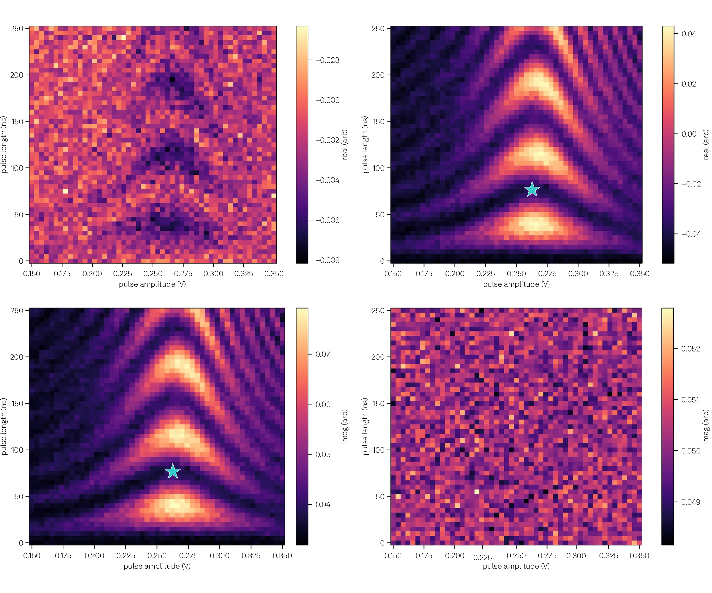
With a fixed coupler-flux pulse-amplitude, we swept the length of both pulses and the amplitude of the qubit flux pulse in a Chevron experiment. The amplitude and length sweep ranges were determined by the relative qubit frequencies compared to their anharmonicity and the expected ~100 ns gate length. For these qubits, the readout was optimized for the maximum amount of |0⟩ and |1⟩ state information to be in the real component, with the |2⟩ state information being largely observed in the imaginary component. This resulted in mirrored Chevron patterns, one in the imaginary component of qubit 3 (which passes through its |2⟩ state) and the other in the real component of qubit 6 (which passes through its |0⟩ state). The optimal length and amplitude to achieve a round-trip oscillation was found to be 76 ns and 0.26 V (blue stars in Fig 3). Chevron patterns were found on all other accessible edges on this QPU before focusing on the q3-q6 edge for further CZ tune-up.
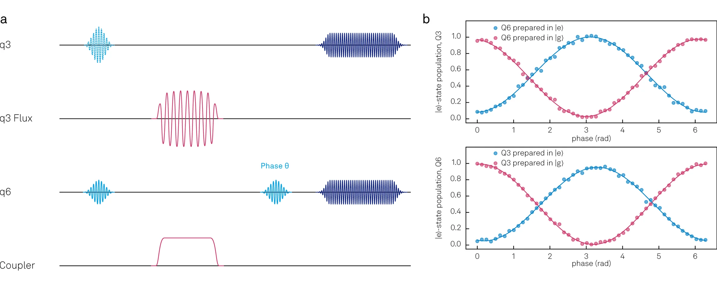
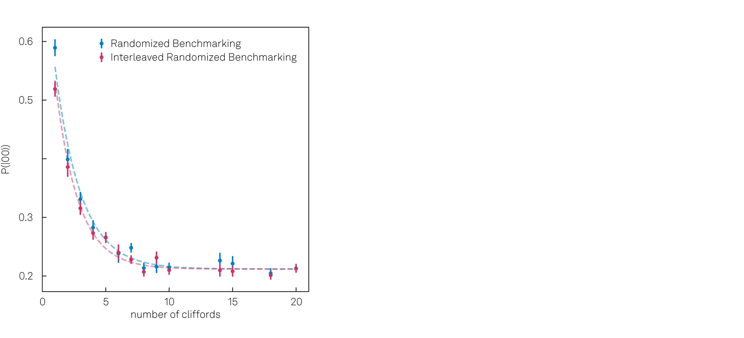
To determine the phase accumulated on both qubits after this CZ gate is applied, we then moved to a conditional-phase calibration Ramsey-like experiment (Fig 4a) at the length and amplitude found in the Chevron experiment (76 ns and 0.26 V). The relative accumulated phase difference on one qubit when the other qubit is in the |0⟩ versus |1⟩ state should be 180 deg, with a virtual Z (vZ) gate applied to ensure no phase is accumulated when the opposite qubit is in the |0⟩ state. This experiment could be done with an additional fine sweep around the pulse parameters found in the Chevron to further optimize the amplitudes and lengths to find exactly 180 deg accumulated phase and minimize |2⟩ state leakage. Here we found a conditional phase of ~175 deg with minimal |2⟩ state leakage which was sufficient to benchmark the gate through interleaved randomized benchmarking (IRB).
Finally, we measured the fidelity of the CZ gate via IRB. Using Qiskit5 to generate the 2Q RB and IRB sequences, we imported them into LabOne Q through our easy-to-use OpenQASM transpiler. The RB sequences are first generated as a set of two-qubit Clifford gates (the 2Q Clifford gates contain both single-qubit and two-qubit operations) randomly selected followed by a recovery gate to return to the |00⟩ state. The IRB sequence takes the same randomly selected Clifford gates and interleaves a CZ between each Clifford gate. The gate errors manifest as a reduced probability that the qubit returns to the |00⟩ state, decaying to a decoherent mix of the four possible states (|00⟩, |01⟩, |10⟩, |11⟩) each with a ~25% population. To extract the fidelity of the CZ gate, following the analysis from this paper, we compare the decay rates of the RB and IRB. For this CZ gate, we observed a fidelity of 95% +/- 2% (Fig 5).
Conclusion and Next Steps
To go from the first initial cooldown to reaching the first CZ gate, a CZ fidelity of 95% on a new QPU is a fantastic starting point. There are several simple strategies we can use to improve this fidelity. We could perform finer flux amplitude and length sweeps (sub-mV and sub-ns), sweep the coupler flux amplitude (here we fixed it to simplify the parameter space investigated in this blog post), optimize the pulse shapes (including applying pre-compensation filters), and apply longer qubit flux pulses combined with shorter coupler flux pulses (to ensure the qubits are at the desired frequencies prior to turning on coupling). Rigetti has shown that when you implement these fine-tuning steps, you can regularly achieve fidelities reaching >99.5% with recent results showing 99.9% when using adiabatic CZ gates. All of these experiments are easily implemented into our automation workflows for the Novera QPU or any QPU of interest. This allows you to simply press run and have a fully calibrated QPU before you finish your first cup of coffee.
Over the course of these measurements, we found the Novera QPU to be an extremely flexible platform for a wide range of experimental applications, but with that flexibility comes added complexity in bringing up the entire chip to its full potential. With LabOne Q’s automation workflow platform and easy-to-modify sequences, this challenge is greatly reduced. Shortening the time it takes to get from your first cooldown to your desired experimental results, allowing you to focus on your scientific goals instead of constant optimization.
Acknowledgements
We thank Rigetti for providing the Novera QPU and measurement time in their labs through the Novera QPU Partner Program. Specifically, we would like to thank Ella Lachman and Andrew Bestwick for providing experimental support, Alex Hill, Ramiro Sagastizabal, and Xian Wu for their theoretical support understanding the new Novera QPU design parameters. At Zurich Instruments, Maya Berlin-Udi and Taekwan Yoon assisted in collecting and analyzing data for this blog post, and many thanks to Emilio Depero and Alastair Marshall for programming support.
If you are interested in performing these experiments on a Novera QPU or another custom QPU design, please get in touch with us. We are happy to share the DAG implementation used in these experiments and learn how we can best support you in overcoming the characterization challenges in your labs.
Technical Tips/Footnotes
- At the time these measurements were performed, the current version of the Applications Library was focused on single-qubit tune-ups. It is constantly being updated and will expand to two-qubit tune-ups for select QPU architectures in the near future. If you have any two-qubit experiments, either included in the blog post or custom to your architecture, please reach out to our application scientists for how to best implement them in LabOne Q.
- The coupler flux voltage needs to be swept at a wide enough range to observe the full coupler frequency range (max coupling at fmax, through the zero-coupling regime, to a non-zero coupling strength at fmin). This can be determined either by predictions based on design parameters or by performing a qubit spectroscopy measurement on a qubit as a function of coupler flux voltage. While not a direct measurement of the coupler frequency, the qubit frequency shifts as a function of the coupler frequency allowing for an analogous range to be found.
- Two notes on the applied qubit flux pulse to realize a resonant CZ gate. First, the qubit flux pulse is modulated at a frequency greater than the anharmonicity of the qubits. On this QPU the qubit anharmonicity was designed to be ~200 MHz. Second, which qubit the flux pulse is applied to depends on the qubit frequency separation and the anharmonicity. A rough calculation of the |11⟩ and |20⟩ energy levels can be done using the sum of the frequencies relative to the ground state. For example, in a case where the qubit frequency difference is greater than the anharmonicity, such as qubits 3 and 6, where the |11⟩ state has a combined “frequency” of 9.25 GHz (q3-ge + q6-ge, or 4.75+4.5) and the |20⟩ state has a combined “frequency” of 9.3 GHz (q3-ge + q3-ef, 4.75 + 4.55). The difference of 0.05 GHz is brought into resonance by applying the flux pulse to q3 to bring its transition frequency down. If the qubit frequency difference is less than the anharmonicity, we need to bring down the lower frequency qubit to bring the |11⟩ and |20⟩ states into resonance.
- A lower voltage would decrease the coupling strength and require a longer CZ gate, taking more time, and a higher voltage would increase the coupling strength lead to a shorter, less-controllable CZ gate, which would be more difficult to optimize.
- In this experiment we used Qiskit to compile the RB and IRB sequences, but with the standardized OpenQASM syntax any higher-level sequence generating software is also compatible with our LabOne Q transpiler.