HDAWG
750 MHz Arbitrary Waveform Generator
Key Features
- 2.4 GSa/s, 16 bits, 750 MHz signal bandwidth
- 5 Vpp maximum amplitude
- Scalable up to 448 output channels
- High channel density
- Less than 50 ns trigger-to-output delay
- Digital modulation at multiple frequencies
- LabOne® AWG Sequencer and Compiler
- Controlled via LabOne®, LabOne Q, or APIs
Variants
Price
CHF 19,400
Pricing shown is ex-works Zurich and only valid for the selected region
Any questions? Contact Us for pricing information
The Zurich Instruments HDAWG multi-channel Arbitrary Waveform Generator has one of the highest channel densities available in its class and is designed for advanced signal generation up to 750 MHz bandwidth. The HDAWG comes with either 4 or 8 DC-coupled, single-ended analog output channels with 16-bit vertical resolution. Output switching is supported between a direct mode with maximized bandwidth and superior noise performance and an amplified mode that boosts the signal amplitude to a maximum of 5 Vpp. Temporal synchronization of up to 18 HDAWGs is supported through the PQSC and up to 56 HDAWGs through QHub.
LabOne provides a state-of-the-art programming concept that combines the performance and flexibility of an arbitrary waveform generator with the accessibility of a function generator. The LabOne user interface, the LabOne Q software framework, and a choice of APIs for Python, C, MATLAB®, LabVIEW and .NET enable measurement automation and fast integration into an existing control environment.
Quantum computing applications:
- Coherent manipulation of qubits with single- and multi-qubit gate operations
- Flux and gate voltage pulse generation with precompensation
- Real-time, low-latency, and global feedback for error correction
Support qubit types:
- Superconducting qubits (transmons, fluxonium, and more)
- Spin qubits
- Color centers (NV, SiV, and more)
Other key applications:
- NMR and EPR spectroscopy
- Radar and Lidar
- Semiconductor testing
Efficient AWG programming
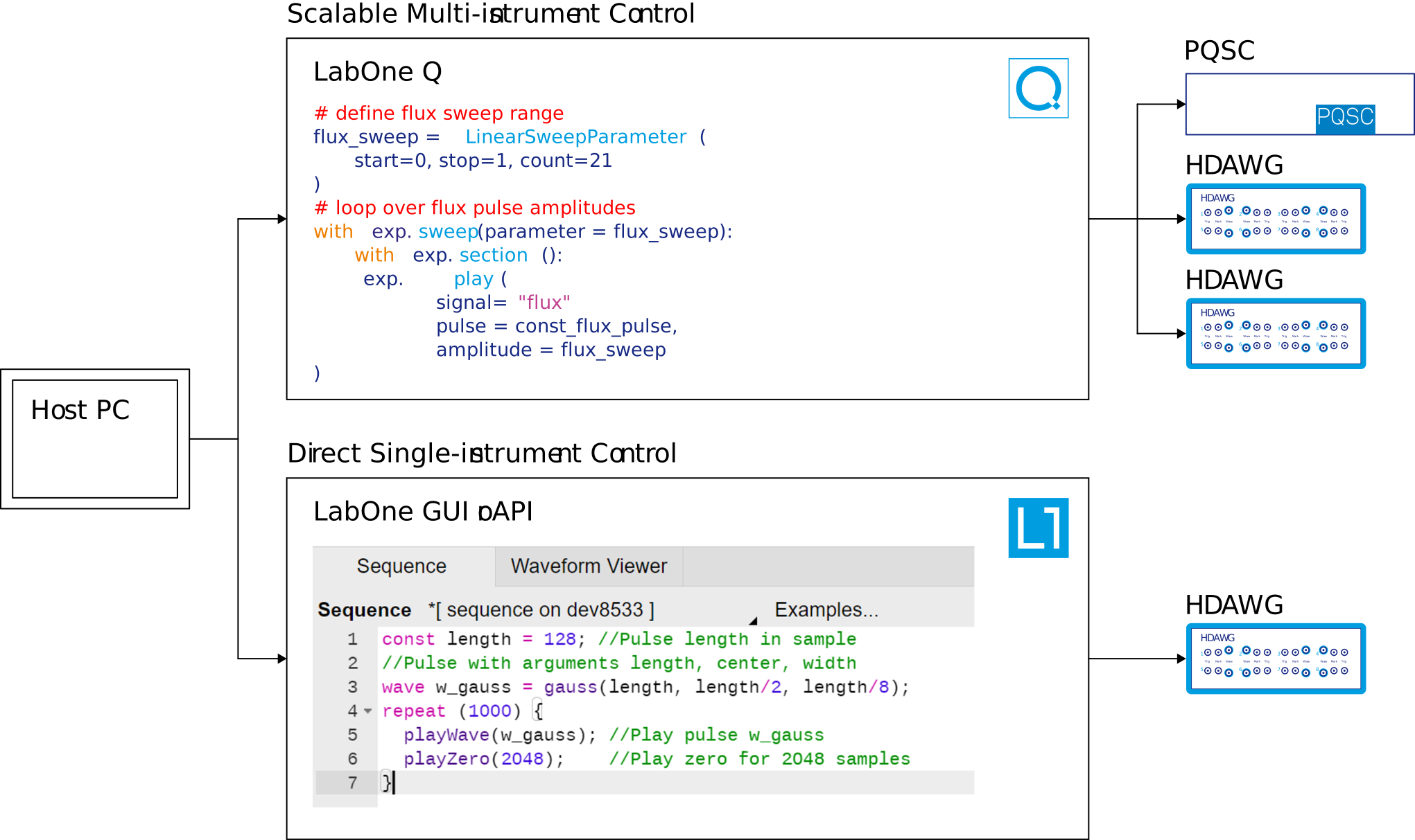
The HDAWG offers two sequence programming interfaces tailored for two main use cases: LabOne Q for multi-instrument setups in quantum computing, and the LabOne AWG Sequencer for single-instrument setups in quantum technology and engineering.
The LabOne AWG Sequencer combines waveform generation, sequencing, and real-time control instructions in one programming language. This approach simplifies signal generation even when complex timing and control flows are needed. The LabOne AWG Sequencer is embedded in the LabOne graphical user interface and is also accessible through APIs in Python, MATLAB®, LabVIEW, and .NET.
LabOne Q provides a full measurement framework for quantum computing that includes pulse sequencing in Python. It automates the synchronization, the programming of multiple instruments of different kinds, and the instrument setting optimization. LabOne Q thereby provides a scalable approach to experiment control.
Oscillators, modulation, and phase control
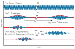
The HDAWG is equipped with digital oscillators to generate the sinusoidal carrier of a signal, independent of the programmed AWG envelope signal. This means that long signals can be generated with very fast waveform upload and precise phase coherence across many pulses. Carrier frequencies and phases that would otherwise be written to a static waveform can be freely adjusted and swept.
The HDAWG-MF Multi-Frequency option increases the number of oscillators and enables full digital I/Q modulation for frequency and phase modulation, frequency multiplexing, or phase cycling.
Scalable system approach
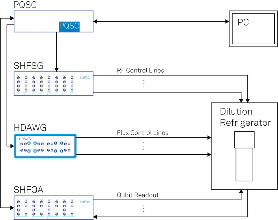
Each pair of channels of the HDAWG has its own AWG core for creating phase- and timing-programmable waveforms, so that a single HDAWG-8 instrument can generate up to 4 IQ signal pairs or 8 real-valued signals.
Multiple HDAWGs can be combined and synchronized in a single setup. The HDAWG can also be matched with any combination of the Zurich Instruments SHFSG, SHFQC, and SHFQA, all of which are controllable through LabOne Q. Such a system could be used for experiments with spin qubits, fluxonium qubits, or flux-tunable transmons coupled to superconducting readout resonators. This can be done by either PQSC or QHub, for systems up to 448 fully synchronized AWG channels.
Low-latency triggering and sequence branching
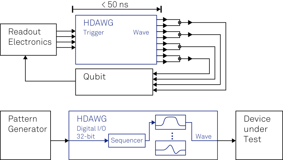
Thanks to the low-latency design, the HDAWG is able to generate its first sample on the signal output less than 50 ns after detecting an external trigger on one of the trigger inputs on the front panel. This is essential for feedback experiments in quantum computing where device properties are short-lived, and each nanosecond that is saved improves the experimental outcome tremendously.
In order to generate signals with a high complexity and real-time control, the HDAWG is able to store up to 1024 pre-stored waveforms in a programmable memory. The HDAWG can then decide which waveforms to play based on the information received over ZSync from a PQSC, on the results of the HDAWG-CNT Pulse Counter option, or on the bit-pattern applied to its 32-bit digital input. The information received in this way could represent a digital modulation pattern, a device-specific test waveform, or a multi-qubit state readout result.
Arbitrary waveform generator
| Channels | 4 (HDAWG4 model) 8 (HDAWG8 model) |
| Vertical resolution | 16 bits (waveforms without marker bits) 14 bits (waveforms with marker bits) |
| Waveform memory per channel | 64 MSa; 500 MSa (with HDAWG-ME option) |
| Sequence length | 16,384 |
| Waveform granularity | 16 samples |
| Minimum waveform length | 32 samples |
| Sequencer clock frequency | Sampling rate divided by 8 |
| Sequencer instructions (playback) | Play waveform (single or multi-channel), play waveform from the library (readout results received over ZSync from a PQSC/QHub or from the results of the HDAWG-CNT Pulse Counter option) |
| Sequencer instructions (other) | Wait constant, wait for trigger, set/get trigger state, set/get DIO state, integer variable operations (add, subtract, logical operations), change oscillator frequency/phase and/or amplitude (real-time), change other instrument setting (non real-time) |
| Sequencer control structures | Repeat (1 to 223-1 or infinite), conditional branch (multi-branch) |
Wave Signal Output
| Connector type | SMA (front panel, single-ended) |
| Output impedance | 50 Ω |
| Output coupling | DC |
| Output modes | Amplified, direct |
| Output range | ±0.1 V to ±2.5 V (amplified, into 50 Ω) ±0.4 V (direct) |
| Output level accuracy | ±(1% of setting + 5 mVpp) (amplified, into 50 Ω) |
| Output level resolution | < 0.1 mV |
| Offset voltage | max. ±1.25 V (amplified, into 50 Ω) 0 V (direct) |
| Offset voltage accuracy | ±(1% of setting + 5 mV) |
| Phase noise | < -135 dBc/Hz (amplified, 1 Vpp, 100 MHz, offset 10 kHz) < -148 dBc/Hz (amplified, 1 Vpp, 100 MHz, offset 1 MHz) < -135 dBc/Hz (direct, 0.5 Vpp, 100 MHz, offset 10 kHz) < -148 dBc/Hz (direct, 0.5 Vpp, 100 MHz, offset 1 MHz) |
| Wave output period jitter | 3 ps RMS (square wave, 150 MHz) |
| Voltage noise above 200 kHz | 35 nV/√Hz (amplified, ±2.5 V range, into high impedance) 12 nV/√Hz (direct, into high impedance) |
| RMS voltage noise (integrated from 100 Hz to 600 MHz) | 320 µVrms (amplified, ±2.5 V range, into 50 Ω) 100 µVrms (direct, into 50 Ω) |
Time- and frequency-domain characteristics
| Wave output bandwidth (-3dB, after correcting for sin(x)/x roll-off) | 0 - 300 MHz (amplified, ±2.5 V range) 0 - 750 MHz (direct) |
| Sampling rate | 100 MSa/s to 2.4 GSa/s |
| Sampling rate divider | 20 to 213 |
| Internal sampling clock resolution | 7 digits |
| Rise time (20% to 80%) | 450 ps (0.2 V step, amplified, ±0.4 V range) 800 ps (1 V step, amplified, ±2.5 V range) 1100 ps (5 V step, amplified, ±2.5 V range) 300 ps (0.8 V step, direct) 550 ps (1 V step, amplified, ±1.5V range) |
| Overshoot | < 1% |
| Trigger delay to output | < 50 ns (within one channel pair 1&2, 2&4, 5&6, 7&8 using playWaveDigTrigger sequencer instruction) < 180 ns (using waitDigTrigger sequencer instruction) |
| Skew between channels | < 200 ps |
| Skew control range | 62 / sampling rate (~25 ns at 2.4 GSa/s) |
| Skew control resolution | 1 sample clock period (~416 ps at 2.4 GSa/s. See also this blog post) |
Marker and other outputs
| Marker outputs | 1 per channel, SMA (front panel), 2 marker bits per waveform |
| Marker output impedance | 50 Ω |
| Marker output rise/fall time | 300 ps (20/80%) |
| Marker output period jitter | 60 ps p-p (square wave, 100 MHz) |
| Marker output skew control | -23...30 ns (range, at max. sampling rate) ~10 ps (resolution, at max. sampling rate, depends on absolute setting) |
| Reference clock output | SMA on back panel |
| Reference clock output impedance | 50 Ω, AC coupled |
| Reference clock output amplitude | 2 Vpp (100 MHz into 50 Ω) |
| Reference clock output frequency | 100 MHz (internal reference mode) 10 / 100 MHz (external reference mode) |
| Reference clock output jitter | 260 fs RMS, derived from integrated phase noise measurement (12 kHz to 200 MHz offset frequency) |
| Sampling clock output | SMA on back panel |
| Sampling clock output amplitude | 0.8 Vpp (2.4 GHz into 50 Ω) 2.0 Vpp (1.0 GHz into 50 Ω) |
Inputs
| Trigger inputs | 1 per channel, SMA (front panel) |
| Trigger input impedance | 50 Ω / 1 kΩ |
| Trigger input voltage range | ±5 V (50 Ω) ±10 V (1 kΩ) |
| Trigger input threshold range | ±5 V (50 Ω) ±10 V (1 kΩ) |
| Trigger input threshold resolution | < 0.4 mV |
| Trigger input threshold hysteresis | > 60 mV |
| Trigger input min. pulse width | 5 ns |
| Trigger input max. operating frequency | 300 MHz |
| Reference clock input | SMA (back panel) |
| Reference clock input impedance | 50 Ω, AC coupled |
| Reference clock input frequency | 10 / 100 MHz |
| Reference clock input amplitude | -4 dBm to +13 dBm |
Oscillators and clocks
| Internal clock type | TXCO |
| Internal clock aging | ±0.8 ppm/year |
| Internal clock short-term stability | 0.0001 ppm (1 s) |
| Internal clock initial accuracy | ±1 ppm |
| Internal clock temperature stability | ±0..3 ppm (–20°C to +70°C) |
| Internal clock phase noise | -105 dBc/Hz (offset 100 Hz) -125 dBc/Hz (offset 1 kHz) |
Maximum ratings
| Damage threshold Wave | -1.2 V / +1.2 V (direct) -6 V / +6 V (amplified) |
| Damage threshold Mark | -0.7 / +4 V |
| Damage threshold Trig | -11 V / +11 V (1 kΩ input impedance) -6 V / +6 V (50 Ω input impedance) |
| Damage threshold Reference Clk In | -4 V / +4 V (DC) +13.5 dBm (AC, with DC offset 0 V) |
| Damage threshold Reference Clk Out | -4 V / +4 V (DC) |
| Damage threshold Sample Clk In | -4 V / +4 V (DC) +13.5 dBm (AC, with DC offset 0 V) |
| Damage threshold Sample Clk Out | -4 V / +4 V (DC) |
| Damage threshold MDS In/Out | -0.7 / +4 V |
| Damage threshold DIO In/Out | -0.7 / +4 V (default configuration 3.3 V CMOS/TTL) |
Connectivity and others
| Digital IO (DIO) | VHDCI 68 pin female connector, 32-bit, configurable as input or output, 3.3 V TTL |
| Host connection | LAN/Ethernet, 1 Gbit/s USB 3.0 |
| PC operating systems | See LabOne Compatibility |
General
| Dimensions | 43.0 × 23.2 × 10.2 cm 16.9 × 9.2 × 4.0 inch, suited for 19 inch rack |
| Weight | 4.6 kg; 10.2 lbs |
| Power supply AC line | 100−240 V (±10%), 50/60 Hz |
| Operating temperature | +5 °C to +40 °C |
| Operating environment | IEC61010, indoor location, installation category II, pollution degree 2 |
| Operating altitude | Up to 2000 m |
HDAWG Q&A
Yes, a 4-channel configuration and an 8-channel one (HDAWG4 and HDAWG8) are available. The HDAWG4 cannot be upgraded to the HDAWG8, and the upgrade options for the two models are not compatible, i.e., it is not possible to install the HDAWG4-PC Real-time Precompensation option on the HDAWG8 and vice versa.
Yes, this instrument is operated from a computer connected via USB 3.0 or 1GbE. The computer uploads waveform and sequence data to the AWG. Once the AWG is started, it generates its signal autonomously and does not strictly depend on the computer anymore.
The LabOne software is freely available in our Download center, with updates appearing on a regular basis. LabOne also provides a single-click function to update the instrument firmware.
Call us on +41 44 515 0410 or send a quick note with your contact details and preferred time slot. We're happy to schedule an online demo to discuss your requirements and check if there is a match with the HDAWG instrument capabilities.
The HDAWG has one marker per channel (4/8 in total). They can be controlled with a timing resolution given by the sampling rate when the marker bit is part of the waveform. See LabOne Q - Triggers and Markers for more details.
Yes, the DIO port can be configured as either input or output in groups of eight bits. They can be controlled via the "setDIO" instruction. As a consequence, the timing resolution of toggling these bits is 150 MHz (6.66 ns), with a minimum of 13.3 ns of time in-between changes. At the moment, the DIO port can be controlled only when the HDAWG is programmed directly in SeqC. The DIO port is functional only when the HDAWG is configured to run at the maximum sample rate of 2.4 GSa/s.
The HDAWG offers triggering possibilities that go beyond the simple triggered mode of other AWGs, and in addition provides pulse counting functionality related to the HDAWG-CNT Pulse Counter option. The HDAWG offers a mode in which pairs of channels (1&2, 3&4, 5&6, 7&8) can be programmed and run as completely independent AWG units. In particular, they can be triggered separately. In addition, a single sequence program can listen to several trigger inputs, e.g. as a line and frame trigger input, and can use the state of a trigger as an input for sequence branching.
Yes, using the PQSC or QHub enables up to respectively 18 or 56 HDAWGs to be synchronized. Alternatively, any combination of HDAWGs, SHFSGs, SHFQAs, and SHFQCs can be synchronized.
All users receive support from Zurich Instruments independently of where the purchase took place. Local sales partners, where available, also provide first-level support in the local language. For extended support, instrument calibration or service, please check the Support page.
The LabOne AWG Sequencer uses a high-level language derived from C - sometimes referred to as seqC - that is natural to read and write. You will thus maintain a much better understanding of what is happening compared to the traditional approach of piling up the sequence as a table of machine instructions. The LabOne sequencer language comes with an integrated waveform generation tool. You can simply define the waveforms in the sequence editor where you need them. Alternatively, the HDAWG can be controlled through one of our APIs for Python, C, MATLAB®, and more to easily integrate it into an existing setup. Finally, our LabOne Q software framework offers a high-level programming experience that automates tasks such as optimizing instrument settings, generating and uploading waveforms, and synchronizing pulses between multiple instruments.
Time-consuming waveform uploads are significantly faster, and the entire sequence definition and variation is much simpler when using signals with a sinusoidal carrier. This is because amplitude modulation makes the carrier independent from the programmed waveform. The carrier parameters (frequency, phase, amplitude, offset) are then adjustable with few mouse clicks.
They increase the flexibility in pattern generation. User registers facilitate variable delays, serve as an index to select a certain waveform, or alter output values on the DIO interface. You can change them manually from the user interface, or perform an automated sweep.
Yes. To include a sequence branch, use an "if" statement in the LabOne sequence program.
Common waveforms (Blackman, Gauss, chirp, sine, square, sinc, DRAG, and more) are available as sequencer commands. You can also add, multiply, cut, concatenate, and scale waveforms, and use loop iterations to generate systematic series of waveforms. You can import your own waveform data too, e.g. by generation of a NumPy or other array in one of the APIs or drag-and-drop of a CSV file in the user interface.
Each instrument is equipped with a country-specific power cable, a USB 3.0 cable, a 1GbE cable, and a printed copy of the quick start guide.
The HDAWG readily supports AM. The HDAWG-MF Multi-Frequency option enables quadrature modulation based on two quadrature channels added up internally. With this technique, it is possible to implement arbitrary modulation schemes that include FM, PM, and DSB.
If you rely on custom MATLAB®, LabVIEW®, Python, .NET, or C software, the integration is straightforward with the LabOne APIs. Additionally, LabOne helps you to find the right API command for a given instrument setting thanks to its command log feature.
The HDAWG provides standard trigger input and output functionalities to synchronize the signal generation of two or more instruments.
No, the HDAWG does not have analog signal inputs and is a pure signal generation instrument – with the exception of the pulse counting functionality that comes with the HDAWG-CNT option.
Waveform data in the CSV (comma-separated value) file format can be uploaded to the HDAWG through drag-and-drop into LabOne.