Why a Lock-in Amplifier Is More Than a Narrow Bandpass Filter
Lock-in amplifiers are often introduced through their effective transfer function: a narrow band around the reference frequency, with a width set by the low-pass filter at the output stage. In terms of magnitude response, this transfer function is essentially indistinguishable from that of a sharp bandpass filter centered at the same frequency. From this picture, a natural question follows: if the two responses look the same, why bother with a lock-in amplifier at all? Why not simply use a good bandpass filter?
The short answer is that two systems with seemingly the same frequency response are not necessarily the same system, especially once noise enters the picture. In real measurements, lock-in amplifiers routinely recover signals that a bandpass filter – even an excellent one – would not be able to extract from the same noise background. The reasons go beyond the frequency-domain picture, and they are perhaps more interesting than one might initially expect.
In this blog post, I would like to look at two distinct ways the analogy between a lock-in amplifier and a bandpass filter starts to break down: implementation and detection structure. As we will see, both eventually trace back to one and the same underlying difference.
How a Lock-in Amplifier Works
Before going further, it is worth recalling what actually happens inside a lock-in amplifier. The architecture is simple: the input signal is multiplied (mixed) with a reference signal at frequency fr, and the result of this multiplication is then passed through a low-pass filter. This mixing-and-filtering operation is known as demodulation, and it is the heart of any lock-in amplifier. In a modern instrument, all these operations are performed digitally. A detailed mathematical treatment of the lock-in detection scheme can be found in our white paper Principles of Lock-in Detection.
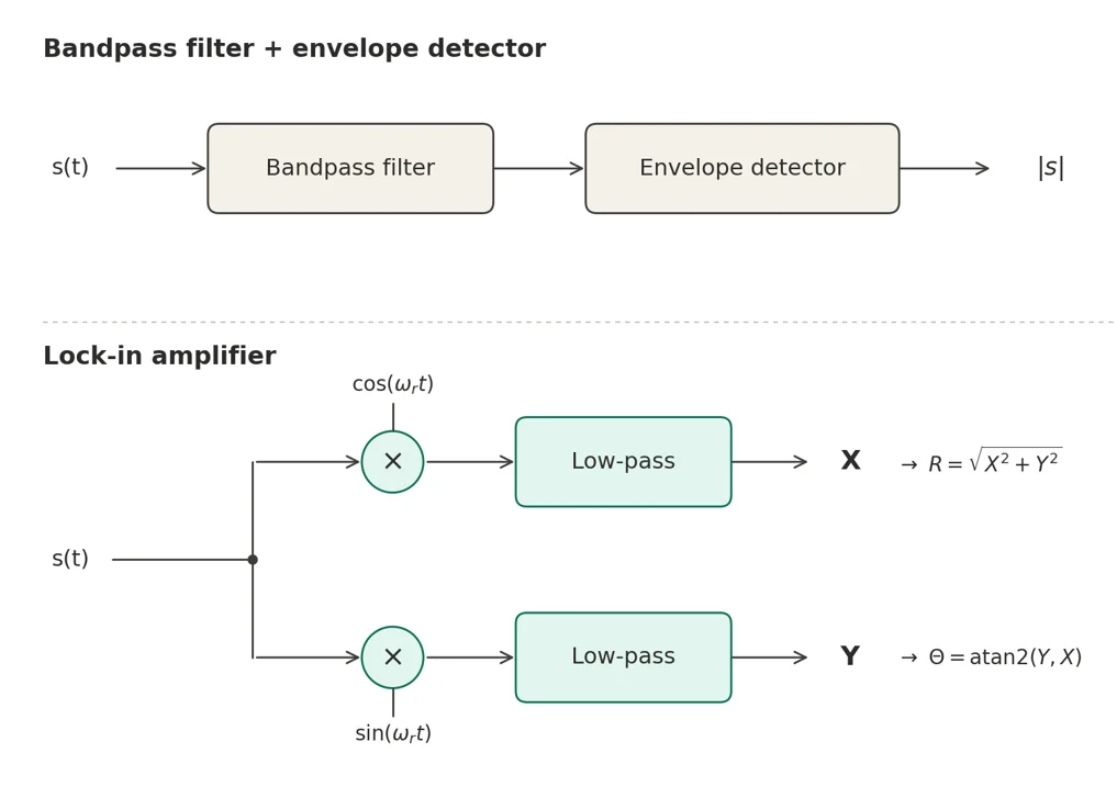
The detail that matters for the rest of this discussion is that the mixing happens twice. The input is multiplied once by the reference cos(ωrt), and once by the same reference shifted by 90°, sin(ωrt). Each branch has its own low-pass filter, and the two outputs are the in-phase and quadrature components, X and Y. For a sinusoidal input at fr with amplitude R and phase Θ, the lock-in produces X = R cosΘ and Y = R sinΘ. The amplitude and phase of the signal are then recovered as R = √(X² + Y²) and Θ = atan2(Y, X). Importantly, X and Y are baseband (DC) signals: they no longer oscillate at the carrier frequency. For this reason, the fair point of comparison for the lock-in is not a bandpass filter alone, whose output still oscillates, but the combination of a bandpass filter followed by an envelope detector, as sketched in Figure 1.
Implementation: The Equivalent Bandpass Filter Cannot Be Built
The first issue with the bandpass analogy is a practical one. The bandpass filter that would be equivalent to a typical lock-in measurement is, in many cases, a filter that cannot easily be realized in hardware.
To better understand why, let's recall that the quality factor of a filter is defined as Q = f0 / Δf, where f0 is the center frequency and Δf the bandwidth. Suppose we want to select a 1 Hz band around a 100 kHz carrier. This already requires Q = 10⁵. For a 1 mHz band around the same carrier, a perfectly reasonable bandwidth for a long-averaging measurement, Q jumps to 10⁸. These values are not easy to achieve practically: they require resonators with very high energy storage relative to dissipation, and they bring a number of practical issues with them, such as tight component tolerances, sensitivity to temperature drift, long settling times, and pickup from mechanical vibrations. High-Q resonators like quartz crystals or MEMS devices can reach Q values between 10⁴ and 10⁶, but they sit at fixed frequencies and cannot be tuned arbitrarily. Moreover, even if such a filter could be built at the right frequency, it would also need to stay there: with Q = 10⁸, a relative drift of one part in 10⁸ – of either the filter's center frequency or the signal itself – is enough to move the signal out of the band.
The lock-in amplifier avoids this problem in an elegant way. By mixing the input signal with a reference at the carrier frequency, the signal of interest is shifted down to DC (i.e., 0 frequency), and the bandwidth-limiting operation then happens with a low-pass filter at DC. Here, the demanding ratio between center frequency and bandwidth disappears altogether: there is no carrier frequency left to divide by, and narrowing the bandwidth no longer requires a more selective resonator, but simply a longer time constant of the low-pass filter. In other words, the selectivity that a bandpass filter must obtain from a resonance, the lock-in obtains from averaging time. Furthermore, since the reference is typically derived from the same oscillator that drives the experiment, the detection automatically follows the signal: if the drive frequency drifts, the demodulation window drifts with it, and the measurement always stays centered on the signal.
It is worth pointing out that this is purely an implementation argument: an ideal bandpass filter would, in principle, provide the same noise rejection. The relevant point is that such an ideal filter cannot be realized in hardware, while the lock-in approach can.
Phase Sensitivity
The second issue is more fundamental, and it concerns information that a bandpass filter simply cannot access.
A bandpass filter is a one-port operation: a waveform goes in, and a filtered waveform comes out. The filter does impart a phase shift, but this shift is a fixed property of the filter, not a measurement of the input signal's phase. There is no phase reference inside a bandpass filter – and indeed, phase is meaningful only as a relative quantity, compared to a reference. A lock-in amplifier carries this reference within itself, in the form of the local oscillator at fr.
With a reference available, the signal can be represented as a vector in the X–Y plane, whose two axes are defined by the reference and its 90° shifted copy. The in-phase and quadrature outputs X = R cosΘ and Y = R sinΘ are simply the Cartesian coordinates of this vector; the amplitude R and phase Θ are its polar coordinates. The two representations carry the same information in different parameterizations.
In practice, how the experimenter uses X and Y depends on what they want to measure. When only the amplitude is of interest, the quantity to read is simply R = √(X² + Y²), which does not depend on the phase of the signal relative to the reference.
A bandpass filter followed by an envelope detector would also produce an amplitude reading; in this regime, the two architectures yield the same kind of measurement, though the bandpass route requires the extra envelope-detection stage to recover the amplitude from the still-oscillating filtered signal, while the lock-in computes R directly from its two baseband outputs. The lock-in's distinguishing advantage in this regime remains the one discussed in the previous section: an effective measurement bandwidth that a bandpass filter cannot reach.
The real divergence between the two architectures appears when the phase itself is part of the measurement – as in impedance spectroscopy, AC susceptibility, or dispersion vs absorption in optical spectroscopy. In such measurements, the lock-in's reference is phase-locked to the drive, and X and Y are read directly as the two pieces of information of interest: the projection of the signal onto the two reference axes is the measurement itself. This mode has no counterpart on the bandpass side: without a reference oscillator, there is no way to separate the in-phase and quadrature components of the response, and the phase information is irretrievable from an envelope-detected output.
When a Bandpass Filter Is Sufficient
None of the above is an argument against bandpass filters in general. There are many situations in which a bandpass filter is the right tool: when the required bandwidth is not extreme, when phase information carries no value, and when an envelope detector's SNR penalty is acceptable. RF front-ends, audio crossovers, and simple tone detectors operate happily in this regime.
It is also worth noting that lock-in amplifiers are typically used together with a modulation scheme, e.g., optical chopping, AC excitation, and similar. In such measurements, the dominant gain over a direct DC approach comes from the modulation itself, and a bandpass-based detector reading the same modulated signal would benefit from it in the same way. What the lock-in adds on top is the narrow effective bandwidth and the phase sensitivity discussed above.
The lock-in amplifier earns its place specifically when one is trying to recover a weak signal at a known frequency from a noisy background – the situation in which precision experiments most often find themselves. In that regime, the structural advantages described here are not a marginal improvement but the difference between a measurement that works and one that does not.
Conclusion
The frequency responses of a lock-in amplifier and a bandpass filter look similar, but the two devices are not equivalent. The lock-in carries a phase-coherent reference at the frequency of interest, while a bandpass filter does not – and this single structural difference enables two distinct advantages: an arbitrarily narrow effective bandwidth and direct access to the phase of the signal. Neither of these can be obtained from a bandpass filter alone, however good. The frequency selectivity looks the same; the underlying operation is not.
Acknowledgment
I want to thank my colleague Mehdi Alem for his valuable feedback on this blog post.