Real-Time Terahertz Spectrometer Enabled by Zurich Instruments
Broadband terahertz (THz) radiation, spanning the range of roughly 0.1–30 THz, is a powerful tool for spectroscopically probing fundamental excitations in matter, including electronic intraband transport, magnons, and phonons in solids. THz spectroscopy can also be combined with techniques such as scattering-type scanning near-field optical microscopy (s-SNOM) and scanning tunneling microscopy (STM) to extend spatial resolution into the nanometer regime.
In this blog post, we demonstrate how Zurich Instruments enables real-time THz spectroscopy with maximum signal-to-noise ratio (SNR). In particular, we show why rectangular boxcar averaging [1] can outperform conventional lock-in detection for chopped pulsed signals, and how the entire acquisition chain can be consolidated into a single Zurich Instruments VHFLI or MFLI lock-in amplifier with the boxcar averaging option, replacing a rack of DAQ hardware and custom software. The experiments were performed in the lab of Tobias Kampfrath at Freie Universität Berlin.
Setup Details and Challenges
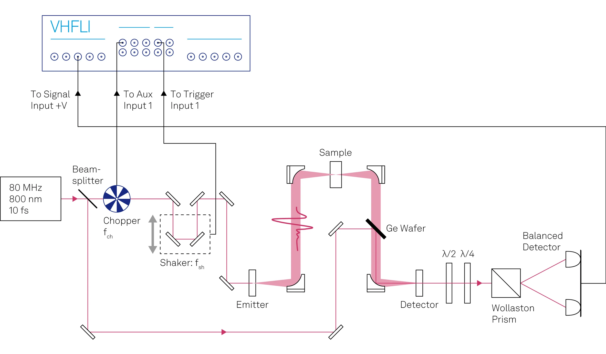
In this experiment, a spintronic THz emitter (STE; T-Spin1 from TeraSpinTec GmbH) serves as a broadband THz source. Excited by a femtosecond laser pulse, it produces a gap-free THz spectrum extending from approximately 0.5 THz to 30 THz [2,3]. The THz electric field is detected by electro-optic sampling (EOS), as shown in Figure 1. The collimated THz beam and a femtosecond probe pulse are focused into a thin electro-optic crystal (10 µm ZnTe), where the instantaneous THz field induces a small polarization rotation and ellipticity in the probe proportional to the electric field [4]. A quarter-wave plate, half-wave plate, and Wollaston prism followed by a balanced photodiode pair convert this induced ellipticity into a differential voltage. By scanning the pump–probe delay, one reconstructs the electric field waveform E(t).
Broadband THz detection presents two main challenges. First, the THz signal, especially at higher frequencies, is weak, so achieving a high signal-to-noise ratio (SNR) is essential. Second, the higher-frequency components of the THz beam are focused more tightly than the lower-frequency components. Recovering the full spectrum therefore requires careful optimization so that all frequency components overlap with the probe in a crystal thin enough to preserve high-frequency phase matching. In practice, this means patiently adjusting many coupled degrees of freedom, including the emitter position and multiple steering mirrors for the pump, THz, and probe beams.
With a conventional slow delay stage, optimization becomes cumbersome: after each alignment adjustment, one must wait for a full delay scan and lock-in settling before knowing whether the change improved the signal. When many parameters interact, reaching the full bandwidth becomes a slow and frustrating process.
The Solution
To address both challenges at once, we combine fast scanning of the whole delay range with fast demodulation with lock-in and boxcar averaging [5]. Fig. 1 shows our setup: fast delay cycling to facilitate parameter optimization and higher signal-to-noise ratio for measuring high-frequency THz components. The signal acquisition is done with a single Zurich Instruments lock-in amplifier and the LabOne software, making the implementation straightforward.
Instead of a stepper-driven delay stage, we use a fast resonant delay line (a Scan Delay from APE GmbH) operating at fsh ≈ 21 Hz. Each half-oscillation corresponds to one full delay scan, yielding approximately 2fsh terahertz waveforms per second. This is fast enough for the waveform on the LabOne screen to update in real time while the user adjusts alignment knobs, turning optimization into an interactive process rather than a slow trial-and-error loop. At each turning point, the Delay stage emits a short trigger pulse that time-references the scans for averaging.
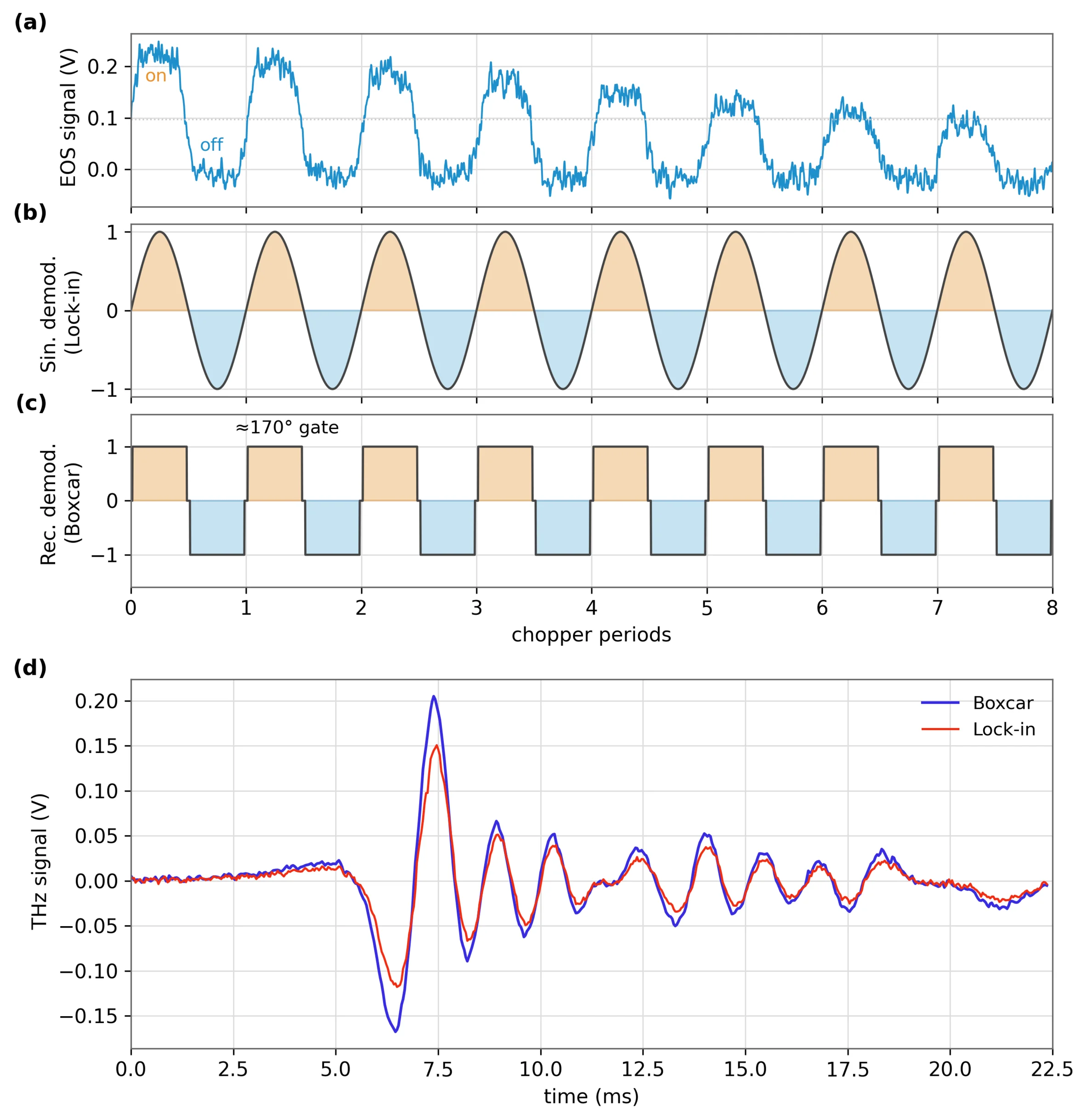
The second key element is the demodulation scheme. The pump beam is modulated with a chopper at 30 kHz. Fig. 2 (a) shows the raw THz signal before demodulation over 8 chopper periods before signal processing. A conventional lock-in amplifier demodulates by multiplying the signal with a sinusoidal reference at the chopping frequency as shown in Fig. 2 (b). For a chopped pulsed signal, however, a rectangular ±1 weighting, phase-locked to the chopper, is a better match. This is precisely what boxcar averaging provides. The important detail is the sign of the weighting: the pump-on half-cycle is integrated with +1, while the pump-off half-cycle is integrated with −1 rather than 0. This means the baseline is subtracted directly inside the boxcar averaging process, suppressing slow drifts and 1/f noise [1]. In practice, a duty cycle slightly below 50% (about 170° instead of 180°) helps avoid artifacts from the chopper switching edges.
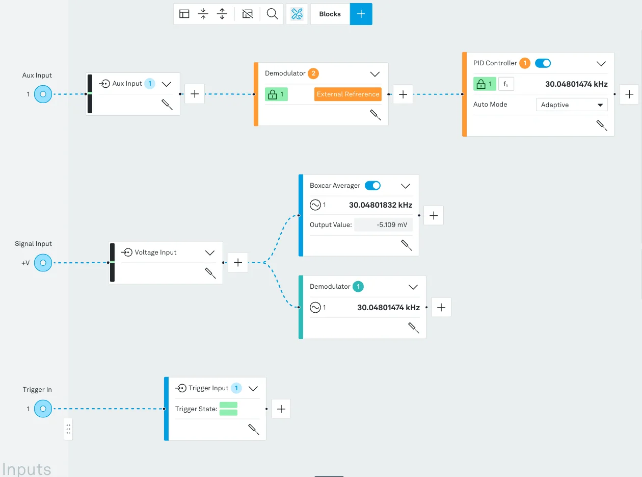
On the VHFLI, this requires only three connections and a straightforward LabOne configuration as shown in Fig. 3. A photodiode monitoring the chopper provides the 30 kHz reference to Aux Input 1, where the external-reference PLL locks Oscillator 1 to the chopper. The balanced detector output is connected to Signal Input 1, while the delay stage trigger is connected to Trigger Input 1 to define the delay axis. The instrument can then be configured to perform standard lock-in detection and boxcar averaging of the input signal simultaneously, phase-coherent with Oscillator 1, while the DAQ module records the boxcar and lock-in outputs versus trigger, one delay sweep per record, averaged over as many sweeps as needed. The configuration in LabOne is shown in Figure 3.
Results
Thanks to the simultaneous measurement with both conventional lock-in detection and boxcar averaging, it is possible to perform a direct comparison of the two methods. The resulting THz signals are shown in Fig. 2 (d). In this experiment, the boxcar method achieves an SNR improvement of about 2 dB over lock-in detection. The horizontal axis initially corresponds to the delay stage real oscillation period. Using the shaker amplitude and the speed of light, this axis can be easily converted into the actual THz waveform time axis in the picosecond range. In the present experiment, the scanned time window spans 5 ps.
Because the delay stage provides about 2fsh=42 sweeps per second and the DAQ module averages them continuously, the THz waveform updates live in LabOne (Video 1). This immediate feedback makes alignment significantly easier.
Live THz Signal Demonstration
To illustrate the real-time capability, we performed a simple lab demonstration shown in Video 1. First, a paper card was inserted into the optical pump path before the emitter. Because the pump light cannot pass through the card, THz generation immediately stopped, and the signal disappeared in real time. Next, the paper was removed from the pump path and placed in the THz beam path after the emitter. In this case, the THz radiation could still pass through the paper, but with attenuation and delay. Accordingly, the waveform displayed in LabOne remained visible, but with a reduced amplitude and a temporal shift. This simple test clearly demonstrates how the live display responds immediately to changes in the experiment.
Video 1. Live THz signal demonstration
Conclusion
A fast resonant delay line operating at about fsh=21 Hz, combined with rectangular boxcar averaging, enables live, high-SNR THz spectroscopy. The delay stage delivers around 2fsh=42 waveforms per second for interactive alignment, while the boxcar suppresses baseline drift and 1/f noise in a single phase-coherent processing step.
Traditionally, this type of experiment requires data acuisition cards together with extensive custom coding for triggering, gating, averaging, and visualization. Here, the same functionality is provided by a single MFLI or VHFLI equipped with the boxcar averaging option, with triggering, averaging, and live display integrated directly in LabOne. Because both conventional lock-in detection and rectangular boxcar averaging are available on the same platform, the two approaches can be compared directly under identical conditions.
Together, these features make it practical to optimize many coupled alignment parameters and recover the emitter’s full bandwidth up to ∼30 THz, while reducing the entire acquisition chain to a single instrument that can also be automated through the LabOne Python API.
Acknowledgements
We thank the Kampfrath group at Freie Universität Berlin, where these measurements were performed.
References
[1] Zurich Instruments, Principles of Boxcar Averaging, white paper.
[2] T. Seifert et. al., Nat. Photonics 10.7 (2016)
[3] R. Rouzegar et al., Phys. Rev. Applied 19.3 (2023)
[4] A. Leitenstorfer et al., Appl. Phys. Lett. 15 (1999)
[5] M. Beck et al., Opt. Express 18 (2010)