Measurement of High-Q Capacitors
Application Description

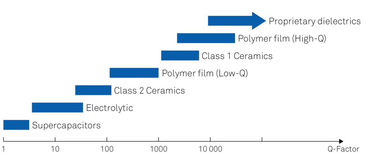
High-performance components are critical when developing faster and smaller electronic devices. A prime example is the capacitor, which is often called upon to ensure an extremely low equivalent series resistance (ESR). Capacitors with this property have a high quality factor Q or, equivalently, low loss or low dissipation D. As Q represents the efficiency of the capacitor, that is, the ratio of energy stored to energy dissipated per cycle, it is related to the ESR (RESR) as Q = 1/(ω C RESR), where ω is the angular frequency and C is the capacitance.
High-Q capacitors are required for RF power stages, demanding filter applications, and as bypass elements. Manufacturing high-Q capacitors requires high-temperature sintering with careful control of the dielectric layer thickness, the dielectric constant of the ceramic material, and the volumetric form factor defining the effective area. This process leads to a manufacturing variability such that even capacitors with the same part number can exhibit very different Q values. For this reason, optimal circuit design necessitates the ability to measure Q, D and the ESR over the full working frequency range of the component.
Measurement Strategies
The Q factor of a capacitor can be measured with a multi-instrument set-up comprising a resonant line, an RF signal generator and an RF voltmeter. This method is not suitable for frequencies below 100 MHz, and requires interpolation and post-processing to extract accurate values. A vector network analyzer can be used between 1 MHz and 3 GHz, but its accuracy is low and post-processing is also required to calculate Q, D, or the ESR.
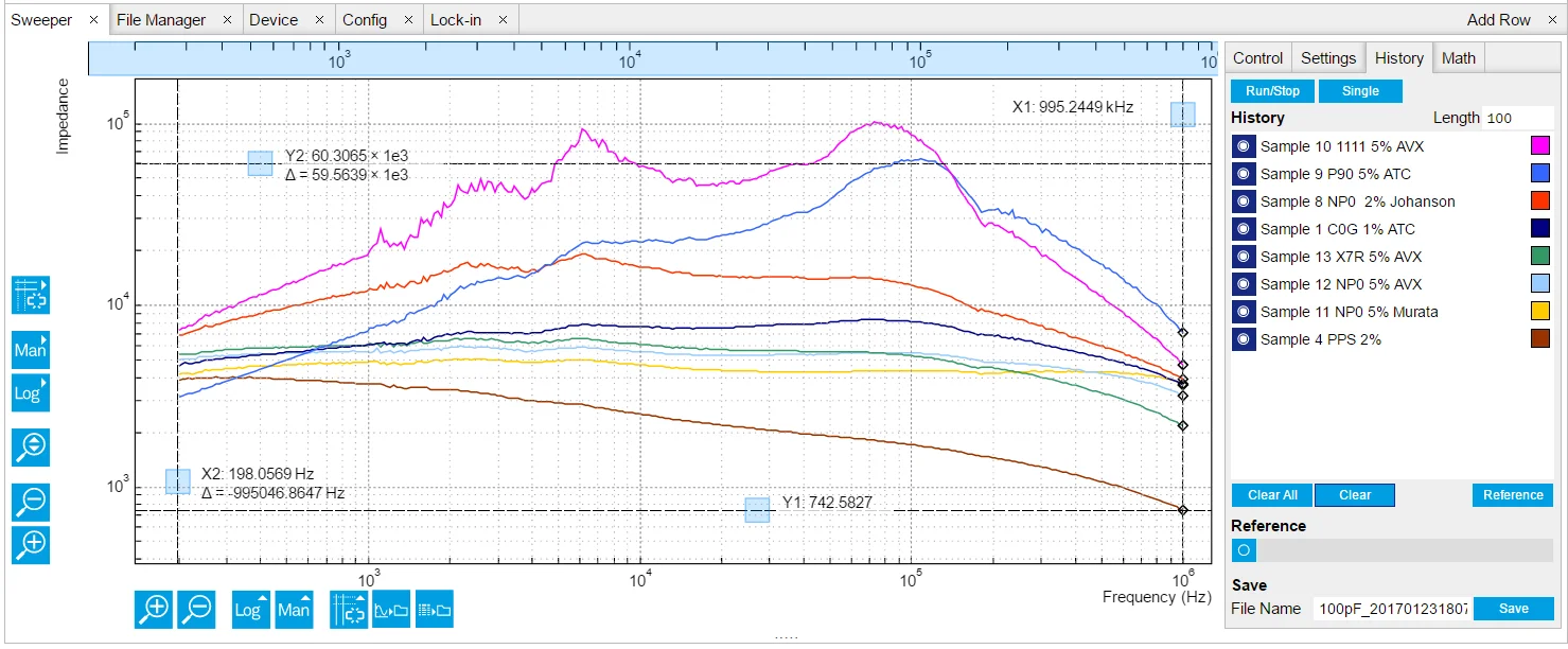
A single-instrument strategy takes advantage of an impedance analyzer such as the MFIA. With the MFIA Impedance Analyzer, it is possible to obtain direct measurements of Q, D and the ESR without calibration. The sample is mounted on a carrier and inserted into the MFITF Impedance Test Fixture as shown in Figure 1. This method is easy to set up and use, and affords high accuracy for frequencies between 1 mHz and 5 MHz. Swept measurements allow Q to be measured as a function of frequency at values over 105 (see Figure 2).
The Benefits of Choosing Zurich Instruments
- You can measure the Q factor, the dissipation, and the ESR of your discrete capacitors accurately and at the operation frequency of your device over the range of 1 mHz to 5 MHz.
- The MFIA comes with the low-parasitic MFITF Impedance Test Fixture to ensure calibration-free measurements, but it is also possible to use your existing third-party fixtures with the user-compensation tool of the LabOne software, which is also included with the MFIA.
- Displaying multiple impedance parameters as a function of frequency is straightforward thanks to the LabOne Sweeper tool, whereas measurements at a fixed frequency can take advantage of the LabOne Plotter tool.
- The MFIA can be integrated into larger setups thanks to the five APIs provided with LabOne.